Posiflex PD-300R User Manual
Page 5
Part 5
PD-303:
1.
Adhere the two pieces of EVA tape on the metal plates at
bottom as indicated in picture at right. Peel off the
protective covers of the tape to stick PD303 series on a
flat and clean surface
.
2.
Apply the screws at 2 arrows in the right picture for firm
fixation on counter if necessary.
PD-305, PD-306, PD-306U:
1.
Remove rear connect cover of the KS or
TP series terminal system from the base
per instruction of the terminal system.
2.
Have the cable of PD-305, PD-306 or PD-306U that
comes out of its base joint to enter the base of host
system through the cable exit so to connect to the
main unit.
3.
Match the base joint of PD-305, PD-306 or
PD-306U to the system rear connect area Fit
2 screws through washers at arrowed points
in the right pictures to hold the joint tight.
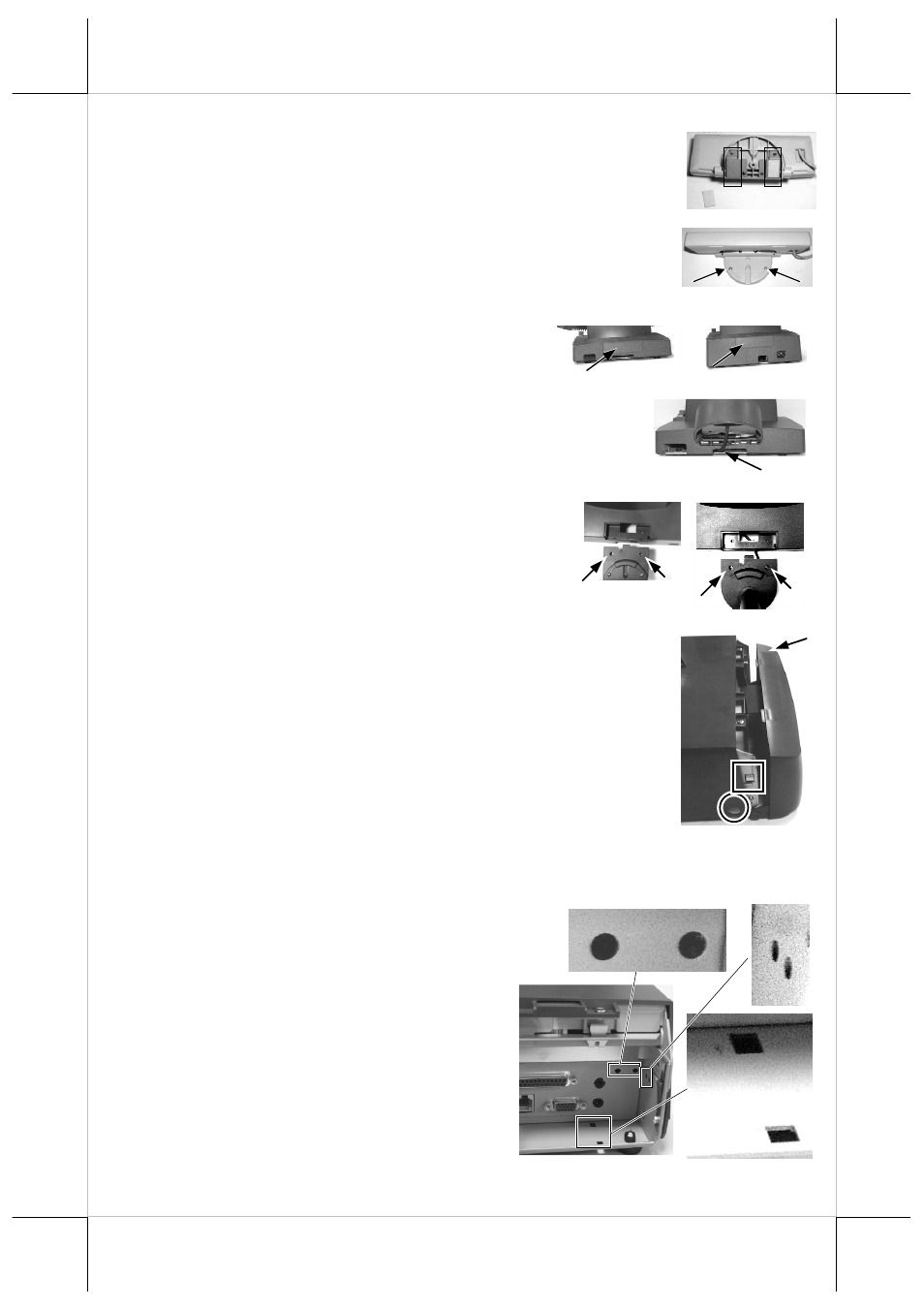
PD-307, PD-307U:
1.
For ease of PD-307 / PD-307U installation operation,
the HT main unit or PB system has to be opened with
sufficient precautions. First push in the circled knobs on
both sides as in the right picture to remove the back
cover. Take out the arrow pointed pole cover from it.
2.
Prepare a piece of clean soft clothe of appropriate size in
front of the HT system to prevent damage to the display
panel. Turn the display panel to straight up position. For
both HT and PB system, push in the rectangular marked spring button in
the same picture mentioned above on both sides of chassis and raise the
rear edge of the top cover. The COM port DC support for PD-307 can be
set at this moment.
3.
Refer to the picture at right of the HT or PB
chassis near the right bottom corner (as you
are facing the HT or PB system from
its back) with 3 enlarged portions
around, please find 2 rectangular PD
installation holes A on the bottom
chassis; 2 circular locating holes B on
I/O plate; and 2 circular screw holes C
on metal sidewall.
PD-305
PD-306
A
A
B
B
C
C
Cable Exit