Start-up & commissioning – Orion System MHGRV III User Manual
Page 14
MHGRV III Controller Technical Guide
Operator Interface
14
Start-up & Commissioning
General
In order to have a trouble free start-up, it is important to follow a few
simple procedures. Before applying power for the fi rst time, it is very
important to run through a few simple checks.
Power Wiring
One of the most important checks to make before powering up the
system for the fi rst time is to confi rm proper voltage and transformer
sizing for the controller. Each MHGRV III controller requires 40 VA of
power delivered to it at 24 VAC.
Check all wiring leads at the terminal block for tightness. Be sure that
wire strands do not stick out and touch adjacent terminals. Confi rm
that all sensors required for your system are mounted in the appropri-
ate location and wired into the correct terminals on the MHGRV III
controller.
After all the above wiring checks are complete, apply power to the
MHGRV III controller.
Power Up and Operation
The MHGRV III Controller uses on-board LEDs to indicate various
diagnostic conditions during power-up and operation. The LEDs are
labeled, “STAT”. Starting with power up, the LED blink codes are as
follows:
STAT on for 10 seconds
STEP on for 10 seconds
STAT b
links 30 times
STEP on for 45 seconds
STAT blinks 3 times rapidly
Status code is repeatedly blinked every ten seconds to
indicate controller status
STEP LED will be on any time modulating valves move
See the Troubleshooting section of this manual for LED diagnostic
code information.
Programming the Controller
Stand-Alone
If the MHGRV III is used as a stand-alone controller, it does not require
programming. It does require the Supply Air Temperature SETPOINT
DIP Switch and the RESET LIMIT DIP Switch (if required) be correctly
set for the required Supply Air Temperature and the Supply Air Reset
Temperature.
When Used with an HVAC Unit Controller
When the MHGRV III controller is connected to an HVAC Unit con-
troller, the HVAC unit controller must be programmed with the desired
Supply Air Temperature Setpoint and Supply Air Temperature Reset
Setpoint and other confi guration information. In order to confi gure and
program the HVAC unit controller, you must have a central operator’s
interface or a personal computer with the Prism II computer front-end
software installed.
Two different operator interfaces are available for programming of the
HVAC unit controller to access the status and setpoints of the HVAC
unit controller—the Modular Service Tool or the Modular System Man-
ager. See the Modular Service Tool and System Manager Programming
Guide for programming information. If you are going to use a personal
computer and the Prism computer front-end software, please refer to the
Prism II Technical Guide. No matter which operator interface you use,
it is recommended that you proceed with the programming and setup
of the controller in the order that follows:
1. Confi gure the controller for your application
2. Program the controller setpoints
3. Review controller status screens to verify system
operation and correct controller confi guration
Modular Service Tool
The modular service tool can be used to check the status of the MHGRV
III board. You can do this if the board is stand-alone or being used with
an HVAC unit controller.
NOTE: Modular Service Tool must have software version 3.30
or later.
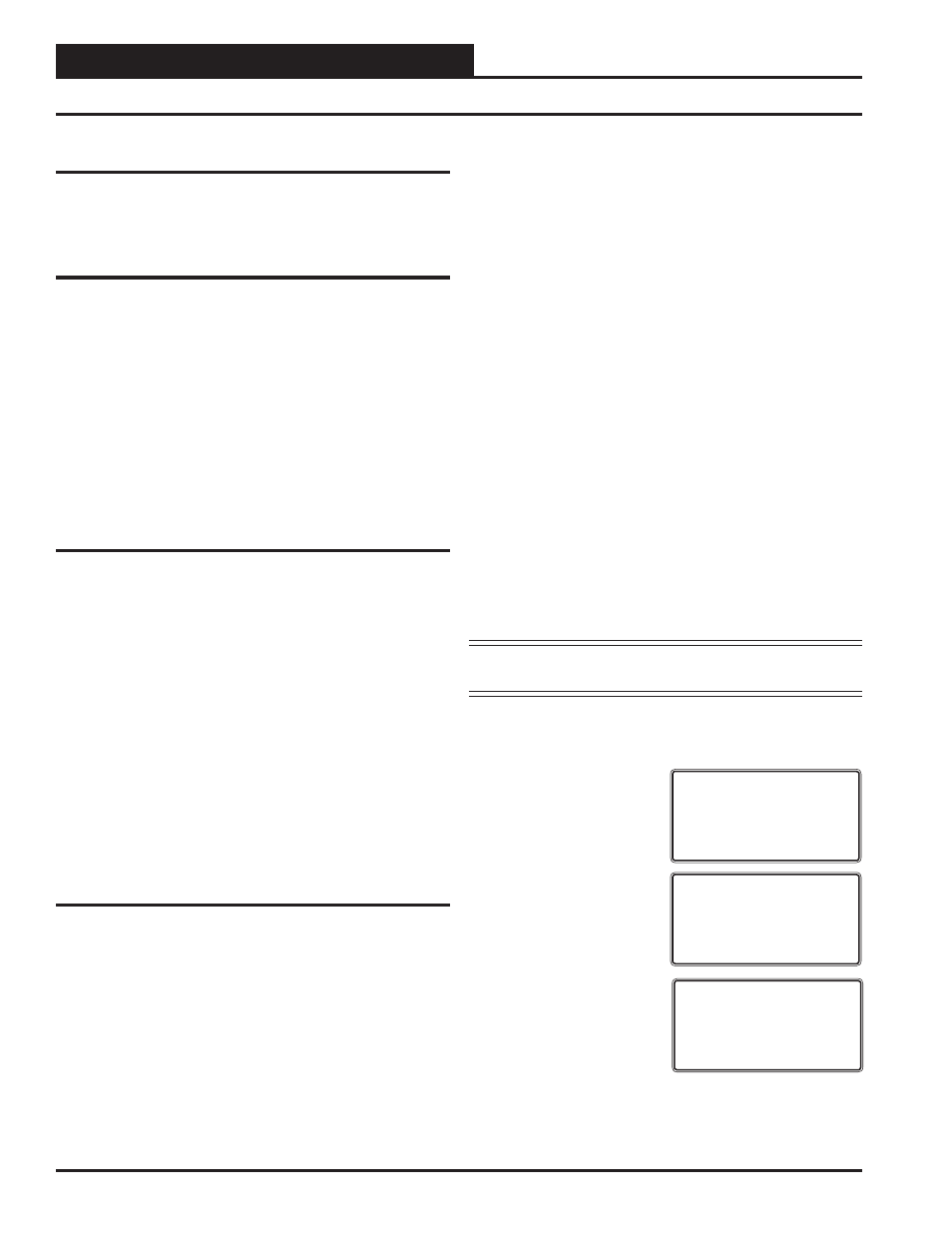
After you press the Status button on the handheld, the following screens
will appear:
Enter 56 for the MHGRV III
board.
If unit has Reheat Active, this
screen will appear:
If Reheat isn’t active, you will
see this screen:
Unit Selection
Enter Unit ID#
Selected ID#: 56
Unit Active
Supply Air: X.XF
Setpoint: X.XF
Valve Pos: X.X%
Unit Off
Supply Air: X.XF
Setpoint: X.XF
Valve Pos: X.X%