Troubleshooting, Technical guide vav/zone controller 22, Using leds to verify operation – Orion System VAV/Zone Controller User Manual
Page 22: Other checks, Figure 12: led locations, Table 5: scan led blink codes, Space temperature sensor
Technical Guide
VAV/Zone Controller
22
Troubleshooting
Using LEDs To Verify Operation
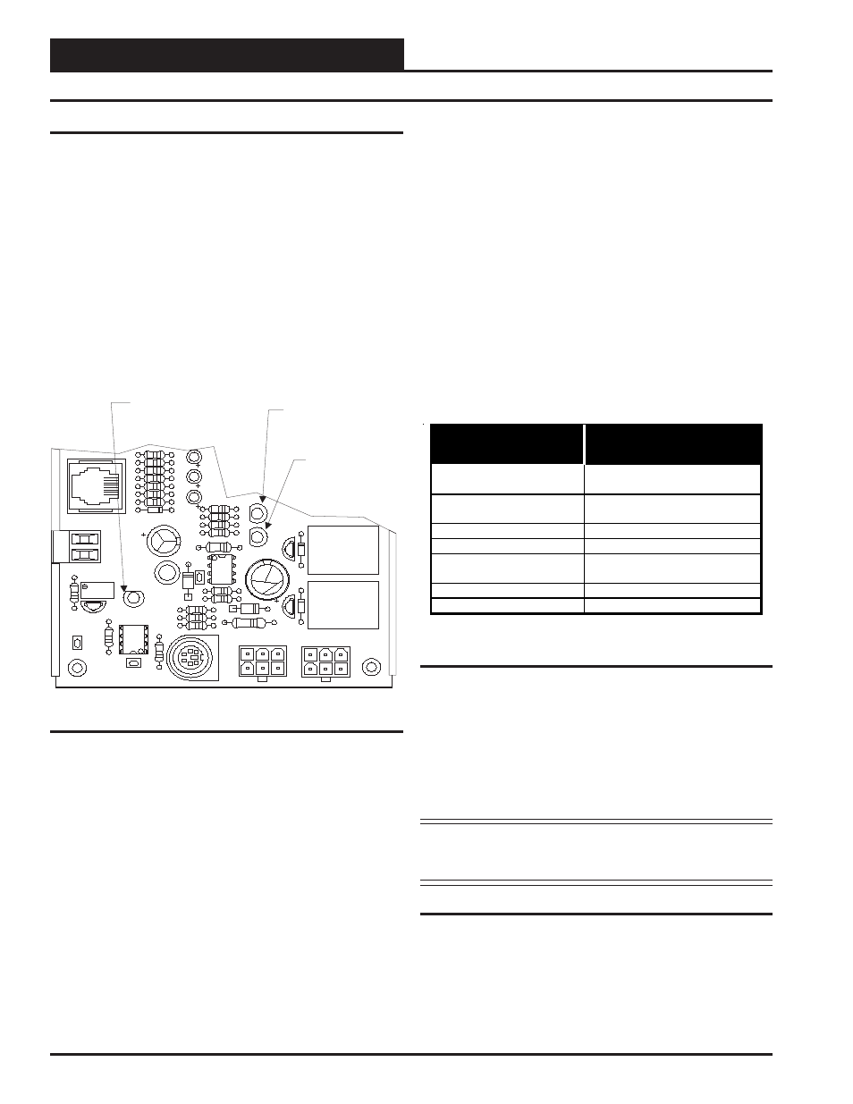
The VAV controller is equipped with LEDs that can be used as very
powerful troubleshooting tools. The VAV/Zone controller board has three
LEDs. Two of these LEDs are used in troubleshooting. See Figure 12
for the LED locations. The LEDs and their uses are as follows:
“REC”
This LED will light up to indicate system communications.
“PWR”
This LED will light up to indicate that 24 VAC power has been applied
to the controller.
“SCAN”
This is the diagnostic blink code LED. It will light up and blink out
diagnostic codes.
SP
ACE
SENSOR
PJ3
D5
C9
C10
C1
1
TB2
AIN
GND
AUX
C13
L1
PWR
RV1
VR1
R33
R10
R14
R15
R19
R20
R18
SCAN
REC
D1
D2
Q1
Q2
U5
C8
R16
C6
D4
D3
R32
R23
U8
CX8
C14
OUT
IN
P1
P2
K1
K2
R36
R35
R37
P3
HAND
HELD
“SCAN”
Diagnostics LED
“REC” LED
“PWR” LED
Figure 12: LED Locations
“REC” LED Operations
When the controller is communicating this LED will flicker. If it does
not flicker check the MiniLink and/or CommLink that is connected to
the Power/Comm board which connects to your VAV/Zone controller
and make sure the MiniLink and/or CommLink is powered up and prop-
erly connected to the Power/Comm board.
“PWR” LED Operations
When the VAV/CAV Controller is powered up the “PWR” LED should
light up and stay on continuously. If it does not light up, check to be
sure that the modular connector is connected to the board, that the con-
nections are tight and the tab is locked on the connector. Be sure power
is connected and turned on to the Power/Comm board and that the modu-
lar cable connector is securely connected. If after making all these checks
the “PWR” LED does not light up, the board is probably defective.
“SCAN” LED Operations
As previously described when the board is first powered up the LED
will do the following:
•
Flashes Once
•
Off for 5 seconds
•
SCAN LED blinks the board address
(Address 14 = 14 blinks)
•
5 second pause
•
20 second time delay - LED blinks 20 times
•
LED blinks slowly as damper moves towards the open
position. The LED blinks fast as the damper moves
towards the closed position.
After the above steps the status code is repeatedly blinked every 10
seconds to indicate controller status. The status blink codes are listed in
Table 5 below in order of priority.
:
LED Blinks This
Number Of Times
Blink Code
Description
1
Normal Operation. No Alarm
Conditions Exist
2 Push-button
Override
Or
Group Override Is Active
3 Communication
Failure
4
Bad Airflow Sensor
5
Bad or Missing
Space Sensor
6 Damper
Failure
7
Damper Feedback Failure
Table 5: SCAN LED Blink Codes
Only the highest priority failure code will be shown. You must correct
the highest priority alarm before other problems will be indicated.
If the “SCAN” LED does not operate as indicated above, first check
the address switch setting. See Figure 10 for correct address switch
setting procedures. If the address switch setting is correct and the
“SCAN” LED still does not behave as indicated above contact Orion
Controls Technical support.
Note: Power to the controller being addressed must always
be cycled after changing address switch settings in or-
der for the changes to take effect.
Other Checks
Space Temperature Sensor
If the Space Temperature Sensor is not reading a valid temperature, first
make sure that the modular cable connector is firmly plugged into the
mating female modular connectors on the board and at the Space Tem-
perature Sensor. Also make sure if a cable coupler is used, that it is
firmly connected. If the problem persists, try swapping the sensor with