ONICON F-1100 Series User Manual
Page 41
11451 Belcher Road South, Largo FL 33773 • USA • Tel +1 (727) 447-6140 • Fax (727) 442-5699 • [email protected]
Turbine Flow Meter Manual 05/14 - 0721-3 / 13518
Page B-2
11451 South Belcher Road, Largo, FL 33773 • USA • Tel +1 (727) 447-6140 • Fax (727) 442-5699
www.onicon.com • [email protected]
04-14
0536-2 / 15950
Installation Hardware Instructions
Standard Installation Kit for Welded Steel Pipe
For F-1100, F-1200 & FB-1200 Series Insertion Turbine Flow Meters
IMPORTANT NOTE
ONICON insertion flow meters are
precision measuring devices that
must be installed according to the
instructions contained in this
document in order to maintain their
accuracy and reliability. Failure to
follow these instructions will result
in erratic operation and reduced
accuracy.
This kit must be installed prior to filling the system, or into a section of pipe that is isolated from
pressure and flow. Once installed, this kit allows for insertion and removal of the flow meter without
a system shutdown.
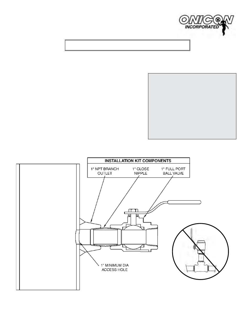
Do not substitute threaded tees for
the welded branch outlet. Contact
ONICON if you need installation
hardware for threaded pipe.
For Use With Kits: INSTL1, INSTL5, INSTL18
Directions:
1. Identify an appropriate location for the flow
meter (see pages 2-4).
2. Weld the branch outlet onto the pipe.
3. Drill a one inch (minimum) access hole,
centered in the branch outlet.
4. Install the close nipple and ball valve as
shown below. Use a paste type thread
sealant. DO NOT use Teflon
®
tape.
5. Flush and fill the system prior to installing the
flow meter.
NOTE: Before installing the flow meter, read the entire installation manual.
(see Sections 3.1 and 3.2).