2 configuration option table – Northern Airborne Technology THxxx User Manual
Page 108
Tac/Com Control Head Manual
SM06 Rev. 4.10
f)
Using the normal editing procedure (SELECT/NEXT), select a valid option for
each feature presented. The configuration mode may not be left until all options
are completed.
g)
It is up to you to ensure that the selected options are compatible with each other
and with the hardware being used. If they are not, the control head may not
operate correctly. Read the following table carefully to ensure that you
understand the configuration options completely.
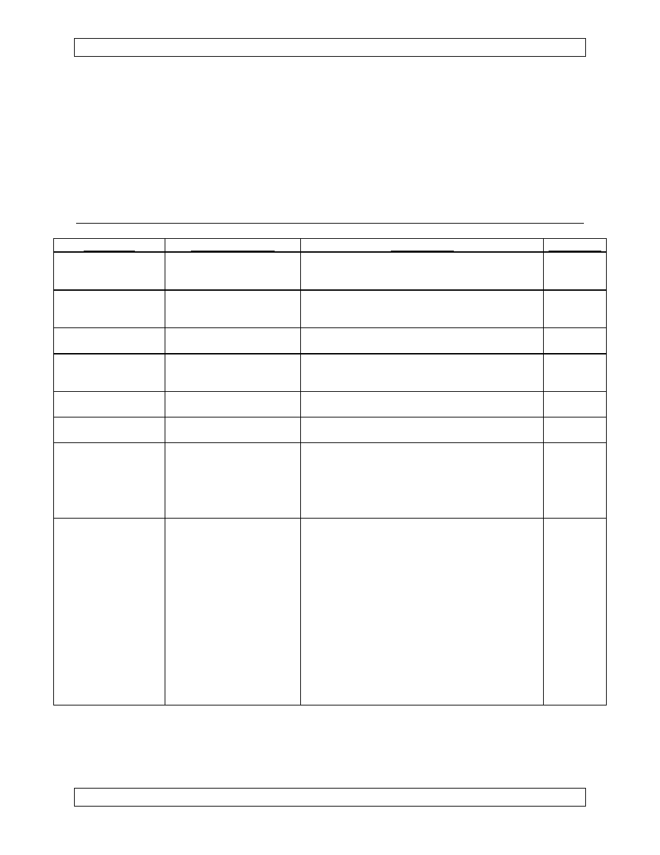
3.12.2
Configuration Option Table
FEATURE
VALID OPTIONS
COMMENTS
S/W VER.*
# OF RADIOS
2,3,4
This is the maximum number of radios the
control head can handle, not the number
installed.
2.00
DIGITAL GRD
or
DPL CODES
ON,OFF
Controls the Digital Channel Guard option for all
NT-series radios installed. (Digital Channel Guard
is also known as Digital Private Line or DPL)
2.00
MASTER C/H
ON,OFF
Determines whether this control head will act as
a master in a master/slave setup. Normally OFF.
2.00
# OF SLAVES
0,1,2
Set to the # of slaves that are connected to this
master control head. This feature supersedes
the MASTER C/H feature.
2.26
STATUS DISPLAY
ON POWER-UP
ON,OFF
Determines whether or not the radio status lines
are displayed on power-up.
2.20
HELP DISPLAY ON
POWER-UP
ON,OFF
Determines whether or not the help information
option is displayed on power-up.
2.47
DATA PAD PORT
0,A,B,C
Set to the serial port that the master control
head's Data Entry Pad is connected to. Set to 0 if
you do not have a Data Entry Pad. Port A is on
the main system connector. Ports B and C are
on the optional auxiliary serial I/O board
connector.
2.26
RADIO
RT-9600, RT-7200,
RT-30, RT-138, RT-450,
450-SYS, RT-406, 406-
SYS, NT30A,
NT30B, NT136, NT150,
NT403, NT450, NT450A,
NT450B, NT450C, NT806,
FF-40,
SYN I, SYN XTR,
2x5,2x5 EXT,PAR BCD,
805-1,
Selects the radio type for each slot.
Make sure that the radio type selected matches
the interface board installed in that slot.
The 450-SYS and 406-SYS options simulate the
C-1000 control head
(with an RT-450 or RT-406F as the UHF RT).
2.00
SPEC L, SPEC L1,
SPEC L2, ASTRO,
NTX138, NTX066,
NTX403
SPEC = SPECTRA, L indicates a standard radio,
L1 indicates control set up with a ‘Zone’ switch,
L2 is Reserved (S/W Ver. 2.44)
Page 3-32
Jan 4, 2006
ENG-FORM: 806-0106.DOT
CONFIDENTIAL AND PROPRIETARY TO NORTHERN AIRBORNE TECHNOLOGY LTD.