4 remote control of flashlink systems, 1 requirements, 2 cable wiring – Nevion D422-MG User Manual
Page 12
D422-MG
Rev. H
nevion.com | 12
4 Remote control of Flashlink systems
For simplicity, this text refers to the card resid
ing local to Multicon as the “local” card and the
one at the other end of the fiber as the “remote” card.
4.1 Requirements
Firmware revision 2.2.0 and FPGA revision 5 is needed on the card that sits local to Multicon
for this feature to work. Any firmware/FPGA revision will work for the card in the remote end.
One RS422 channel (out of 2, 4 or 8 depending on backplane type) needs to be available. It
must be the same channel for both cards, local and remote. The local card needs to be set
up through the debug interface of Multicon (or PC with RS422 and serial port software).
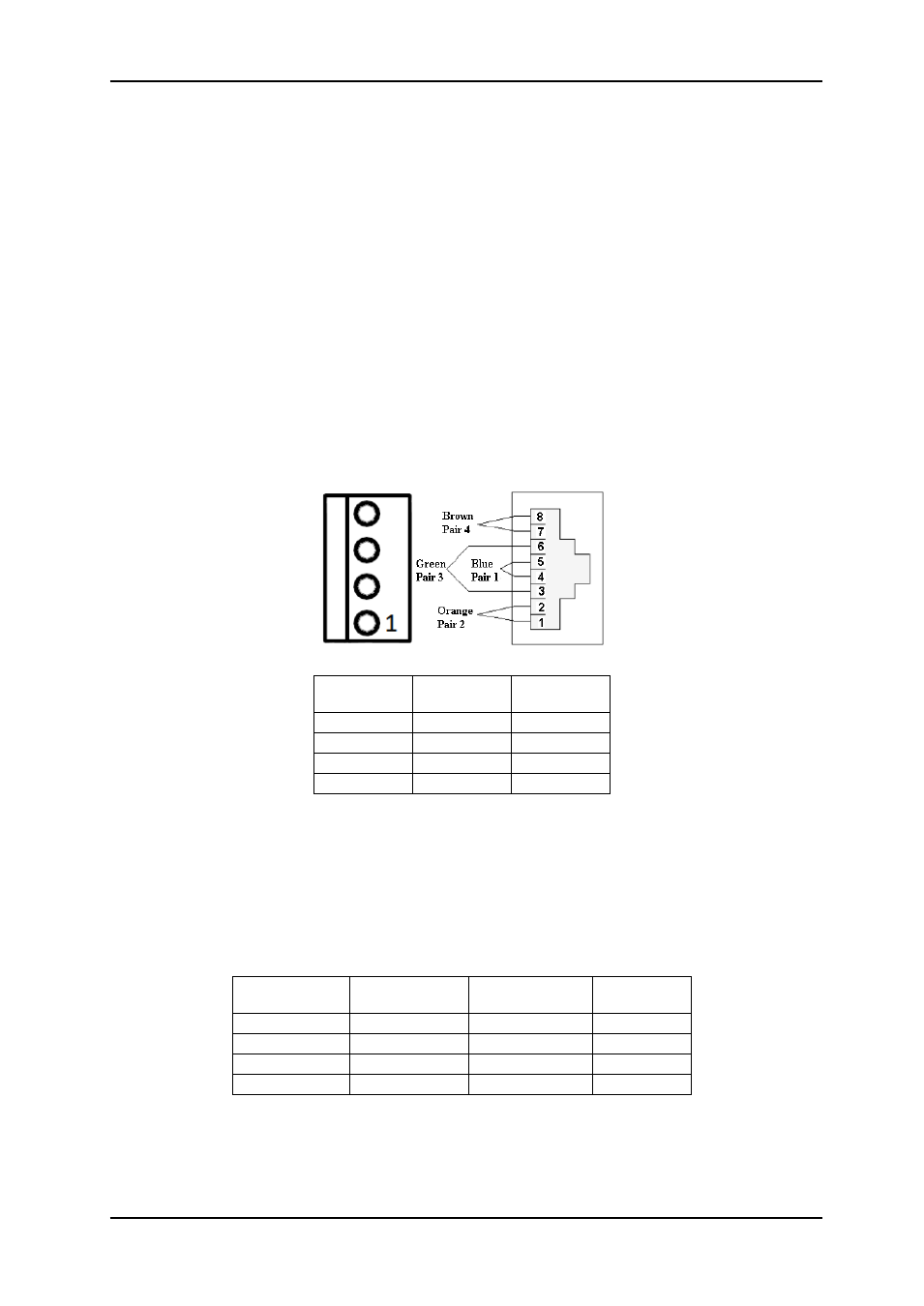
4.2 Cable wiring
The local card is connecting as a normal Flashlink card, talking to Multicon. But we use an
external cable to transmit data from Multicon directly to the fiber. Data from the fiber is
transmitted by the on-board MCU on the internal flashlink bus. Therefore, we only need 2
wires, RX+ of D422-MG is connected to RX+ of the flashlink frame, and likewise with RX-.
C3 and C1 backplane connections, local card
The remote card operates differently, here everything is done in the FPGA and both RX and
TX are done over the external connectors . This D422-MG repeats requests from Multicon to
the cards and responses from the cards to Multicon. Thus, for this end, RX of D422-MG
needs to be connected to TX of the flashlink frame, and TX connected to RX. Always make
sure + connects to + and - to -.
C3 and C1 backplane connections, remote card
D422-MG-
C3
D422-MG-
C1
Flashlink
subrack
1
3
1
2
6
2
-
-
-
-
-
-
D422-MG-C3
D422-MG-C1
(Port 1,3,5,7)
D422-MG-C1
(Port 2,3,6,8)
Flashlink
3
5
7
1
4
4
8
2
1
3
1
3
2
6
2
6