8 c2 db25 connector pin assignments, 9 c3 molex kk connector pin assignments – Nevion D422-MG User Manual
Page 10
D422-MG
Rev. H
nevion.com | 10
3.8 C2 DB25 Connector Pin Assignments
When sold with the C2 backplane, a subset of the inputs and outputs are available on a
single DB25 connector with the following pinout:
Signals marked as inputs on the D-422-MG shall be connected
to the outputs of the connected devices, and vice versa. Note
that when connecting an active device instead of a straight-
through cable between a VTR master and slave (device and
controller), one end of the active device must use a crossed
cable (the VTR slave inputs are named TX and outputs are
named RX).
The GPI inputs are internally connected to +5V via a pull-up
resistor. The inputs will be activated when pulling them to
Ground.
The GPI outputs are of open collector type. An output can
switch a maximum load of 100mA at 30V.
Any device to be controlled by the GPI outputs (lamp, LED or
similar) needs to be connected to an external supply voltage on
one end and to the GPI output on the other end.
Ground is available on the following pins: 2, 5, 8, 11, 13, 16, 19, 22, 25 and on the connector
chassis.
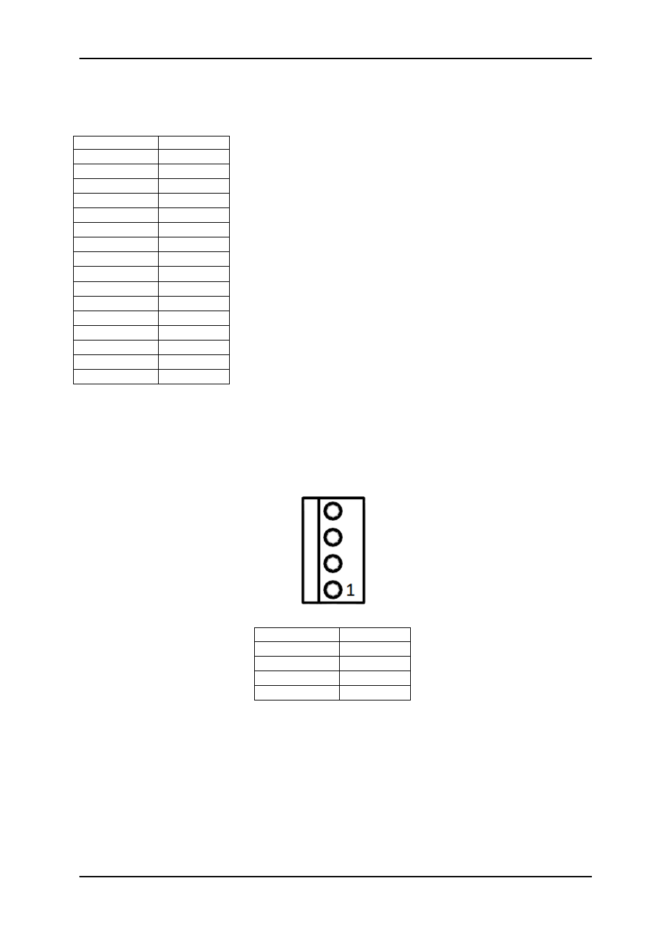
3.9 C3 Molex KK Connector Pin Assignments
When sold with the C3 backplane, a subset of the inputs and outputs are available on a
several Molex KK connectors with the following pinouts:
RS422 connectors
Signals marked as inputs on the D-422-MG shall be connected to the outputs of the
connected devices, and vice versa. Note that when connecting an active device instead of a
straight-through cable between a VTR master and slave (device and controller), one end of
the active device must use a crossed cable (the VTR slave inputs are named TX and outputs
are named RX).
Note that the RS232 ports 1 and 2 are unused when used with D-422-MG module
Output
Pin
TX1+
1
TX1-
14
RX1+
15
RX1-
3
TX2+
4
TX2-
17
RX2+
18
RX2-
6
GPI IN1
7
GPI IN2
9
GPI IN3
10
GPI IN4
12
GPI OUT1
20
GPI OUT2
21
GPI OUT3
23
GPI OUT4
24
Output
Pin
RX+
1
RX-
2
TX+
3
TX-
4