Indicator panel, Figure 8: rt-3020 indicator panel – NavCom RT-3020 Rev.F User Manual
Page 39
RT-3020 User Guide – Rev. F
9 Pulse delay, default 0mS, range 0 – 999mS
9 Rising or Falling Edge Synchronization
A BNC female connector provides the 1PPS output
pulse. A 3ft (0.9m) long, BNC male to BNC male
cable (P/N 94-310050-3003) is available from
NavCom.
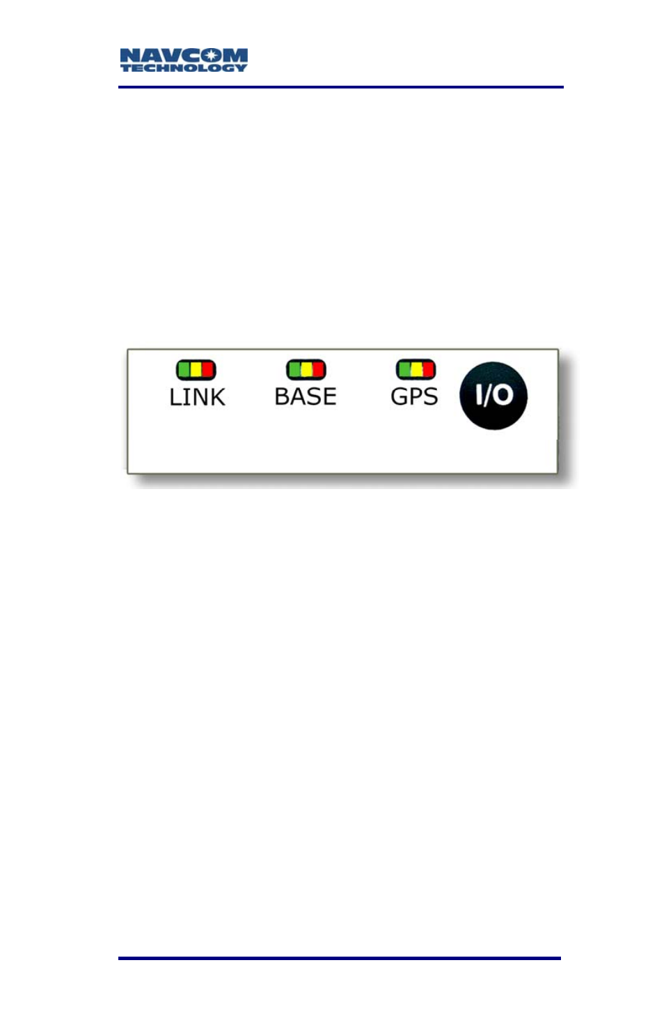
Indicator Panel
Figure 8: RT-3020 Indicator Panel
The indicator panel provides a quick status view of
the base radio signal strength (Rover Mode), base
station correction type, GPS navigation/operating
mode, and the On/Off (I/O) switch, respectively. Each
set of indicators has three LEDs.
To power the unit on or off, depress the I/O switch for
more than 3 seconds. All LEDs illuminate for a period
of 3-5 seconds during power-up of the GPS sensor.
Link
LEDs
The Link LEDs are software
configurable via the x3f proprietary
command. The factory default
configuration is Rover Mode. The Link
LEDs are not used in Base Mode.
2-37
- SF-3050 Logging Data to Internal Memory SurvCE (4 pages)
- SF-3040 Logging Data to Internal Memory or SD Card (6 pages)
- SF-3050 Logging Data to USB Using SurvCE (4 pages)
- StarFire over IP (5 pages)
- SF-3050 Quick Start (4 pages)
- SF-3050 A Computationally Efficient Ambiguity Resolution (7 pages)
- StarFire (5 pages)
- StarFire to SW v3.0.12.0 (3 pages)
- SF-3050 Rev.I (196 pages)
- StarUtil-3000 Rev.G (177 pages)
- Sapphire Rev.L (450 pages)
- StarUtil-3000 Rev.A (119 pages)
- SF-3050 Rev.A (169 pages)
- SF-3050 Rev.B (201 pages)
- SF-3050 Rev.D (235 pages)
- Rinex Utility Rev.D (17 pages)
- SF-3040 Quick Start (4 pages)
- SF-3040 Rev.F (217 pages)
- SurveCE Integration Rev.A (150 pages)
- Install Utility Rev.C (26 pages)
- LAND-PAK Quick Start Rev.B (7 pages)
- LAND-PAK Rev.E (156 pages)
- StarUtil Rev.C (58 pages)
- LAND-PAK Rev.N (194 pages)
- StarUtil Rev.B (8 pages)
- StarUtil Rev.F (134 pages)
- SF-2040 Rev.E (63 pages)
- RT-3010 Rev.E (61 pages)
- StarFire Satellite Change Rev.G (24 pages)
- StarFire Satellite Change Rev.I (23 pages)
- TS Collecting Receiver (2 pages)
- TS Factory Default (2 pages)
- SF-2040 Rev.C (178 pages)
- LAND-PAK Rev.F (159 pages)
- SF-2040 Rev.F (93 pages)
- SF-2110 Quick Start Rev.A (2 pages)
- StarPac Rev.A (15 pages)
- StarControl Rev.C (56 pages)
- SF-2050 Rev.F (99 pages)
- TruBlu Rev.A (2 pages)
- VueStar Rev.B (13 pages)
- SF-2110 Rev.B (99 pages)
- StarUtil-2110 Rev.A (85 pages)
- RT-3010 Rev.F (89 pages)