24hfu – MovinCool 24HFU Service Manual User Manual
Page 36
MOVINCOOL 24HFU / 24HFU-1 SERVICE
PAGE 36
REPAIR - INSPECTION AND REPAIR OF ELECTRICAL SYSTEM • 24HFU
4-2.
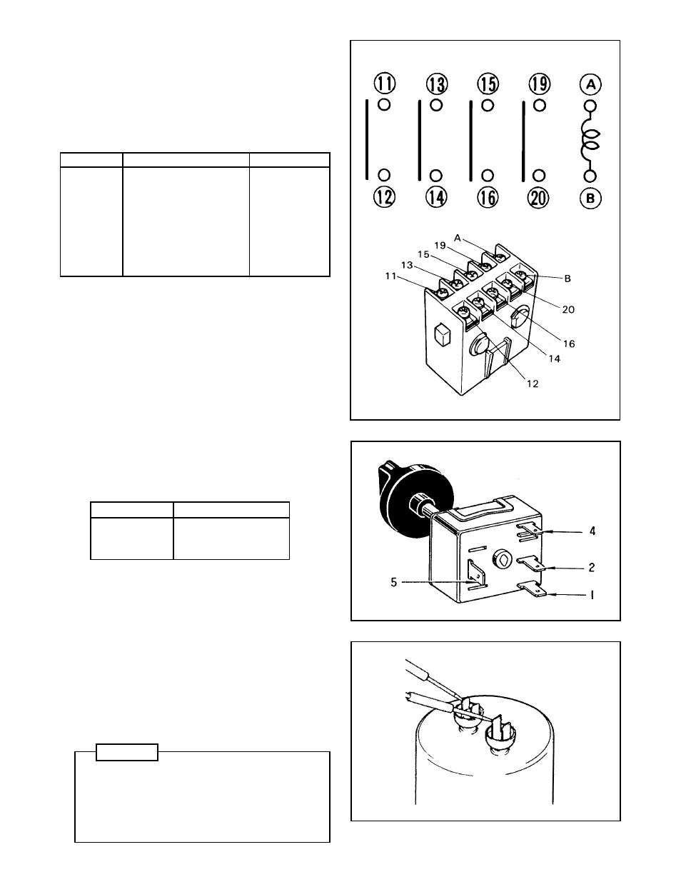
Inspection of Control Switch
At each position of the control switch, there
should be continuity across the following
terminals.
Switch Position Conducting Terminals
OFF
2 - 5
FAN
1 - 5
COOL
1 - 5, 4 - 5
If there is no switch continuity, replace the
control switch.
■ Inspection of Control Switch
4-3.
Inspection of Capacitor (for Fan Motor and
Compressor)
Set the ohmmeter to 100 KW range. Place two
probes against the two terminals of the capaci-
tor. At first, the ohmmeter should indicate 0
Ω
,
then the meter reading should gradually ap-
proach infinity. If the ohmmeter indicates infinity
from the first or the meter reading fails to move
from 0
Ω
, replace the capacitor.
■ Inspection of Capacitor
4-1.
Inspection of Auxiliary Relay
Check for continuity across the terminals when
the test button is depressed and when it is
released.
■ Inspection of Auxiliary Relay
Terminals
State of Reset Switch
Continuity
11-12
Depressed
Conduct
Released
Not Conduct
13-14
Depressed
Conduct
Released
Not Conduct
15-16
Depressed
Conduct
Released
Not Conduct
19-20
Depressed
Conduct
Released
Not Conduct
Measure the resistance across terminals
A and B. Standard resistance: 1900~2100
Ω
When the resistance is out of this range, replace
the auxiliary relay.
24HFU
WARNING
Before and after testing the capacitor for the fan
motor and compressor, proper discharging of
electrostatic charge should be performed by a
qualified service technician. Improper discharge
of the capacitor can cause electrical shock or
death.