Electrical system • 24hfu – MovinCool 24HFU Service Manual User Manual
Page 14
MOVINCOOL 24HFU / 24HFU-1 SERVICE
PAGE 14
ELECTRICAL SYSTEM • 24HFU
4-2.
Control Box
4-2-1.
Capacitor
The capacitor is used to boost power
output to the fan motor and the compres-
sor at start-up.
The specifications of each capacitor are
shown below.
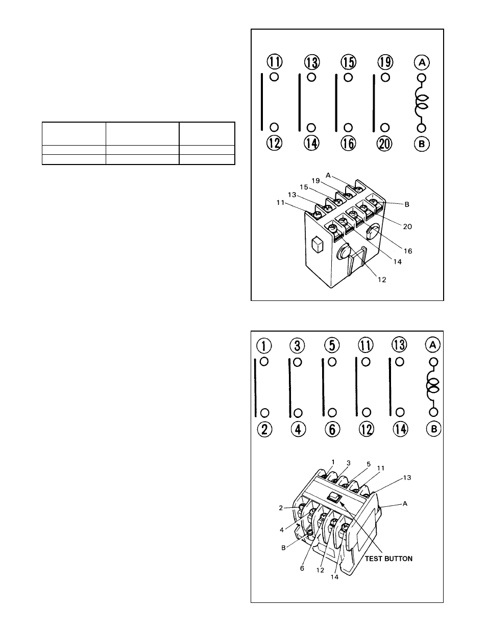
■ Circuit of Auxiliary Relay
■ Auxiliary Relay
4-2-2.
Auxiliary Relay
This auxiliary relay is normally closed
when the unit is in operation (FAN or
COOL), and supplies power to the com-
pressor relay and the fan motor. In the
following cases, however, the relay opens
to interrupt power to the compressor and
the fan motor.
• When the drain tank is filled with water.
(Drain switch OFF.)
• When the high pressure becomes
excessively high. (High pressure switch
OFF.)
When current flows across A and B,
terminals 11 and 12, 13 and 14, 15 and
16, 19 and 20 conduct.
Specifications:
Rated Voltage
AC 240V
Rated current
15 amps
UL Listed File No.
E112482
Capacitor
Registrant Voltage
Capacitance
(Volt)
(mF)
For fan motor
440
12.5
For compressor
370
40
4-2-3.
Compressor Relay
The compressor relay is closed when the
unit is operating in COOL mode, and
supplies power to the compressor. How-
ever in the following cases, the relay
opens to cut off power to the compressor.
• When the auxiliary relay is opened.
(Drain switch OFF or high pressure
switch OFF.)
• When the evaporator has frosted.
(Thermostat OFF.)
Specifications:
Rated Voltage
AC 230V
Rated Current
30 amps
UL Listed File No.
E43028
■ Circuit of Compressor Relay
■ Compressor Relay