Operating instructions, Unpacking and cleaning, Extension cords – Delta 36-841 User Manual
Page 5: Foreword
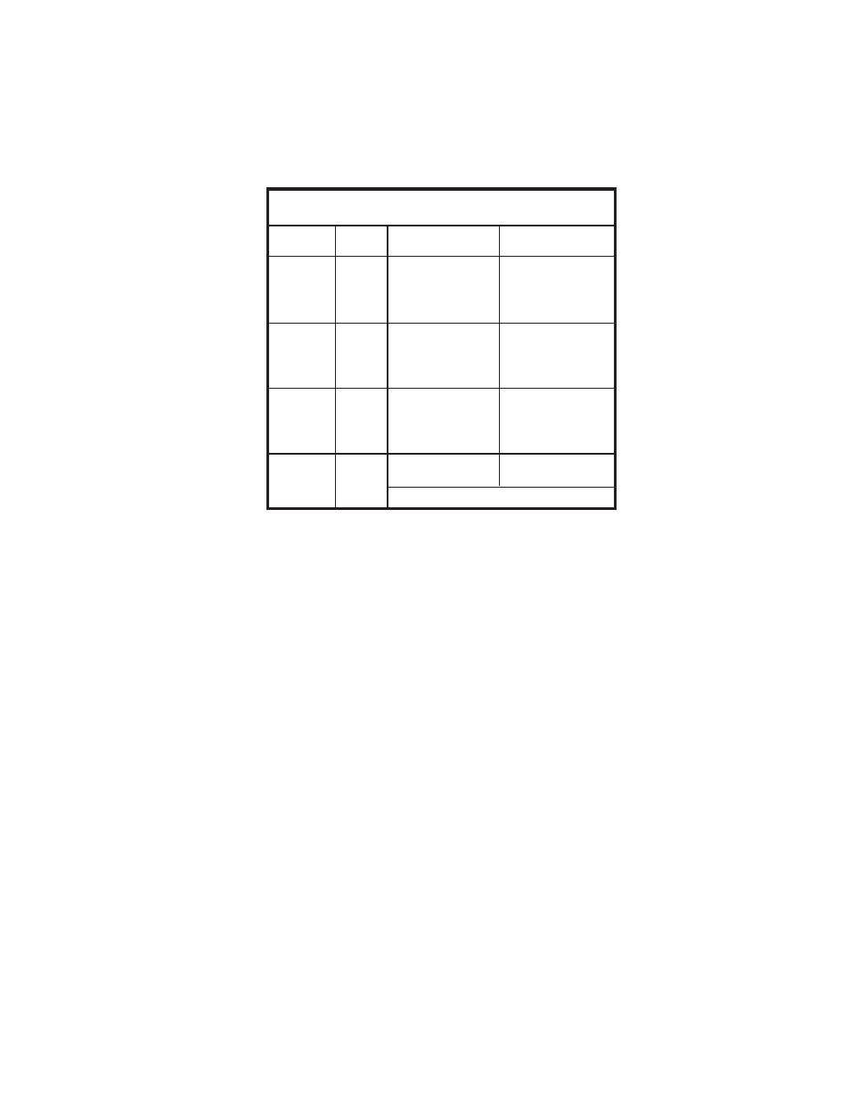
Use proper extension cords. Make sure your extension cord is in good condition and is a 3-wire extension cord which
has a 3-prong grounding type plug and matching receptacle which will accept the machine’s plug. When using an
extension cord, be sure to use one heavy enough to carry the current of the machine. An undersized cord will cause
a drop in line voltage, resulting in loss of power and overheating. Fig. D, shows the correct gauge to use depending
on the cord length. If in doubt, use the next heavier gauge. The smaller the gauge number, the heavier the cord.
EXTENSION CORDS
OPERATING INSTRUCTIONS
FOREWORD
The Limited Edition 10" Unisaw is available with either the 52" Unifence Saw guide, or the 50" Commercial Biesemeyer
Fence system. The Limited Edition 10" Unisaw is a very powerful machine. The motor is single phase, 3 horse power,
230 volt motor that turns the circular blade at 4000 RPMs. The Unisaw is a versatile machine, in that it can do precision
ripping, cross-cutting, dadoing, moulding and tenoning.
UNPACKING AND CLEANING
Carefully unpack the machine and all loose items from the shipping container(s). Remove the protective coating from
all unpainted surfaces. This coating may be removed with a soft cloth moistened with kerosene (do not use acetone,
gasoline or lacquer thinner for this purpose). After cleaning, cover the unpainted surfaces with a good quality household
floor paste wax. Figures 1 and 2, illustrate the saw and all loose items supplied with the machine. Figs. 3, 4, and 5,
illustrate the items supplied with the fence system.
IMPORTANT: The saw is shipped with the saw arbor in the 45 degree position. NOTE: THE HAND WHEEL MUST BE
ASSEMBLED TO THE SAW, SEE THE SECTION “ASSEMBLING BLADE TILTING MECHANISM”, THEN PROCEED
WITH THE FOLLOWING. Loosen locking knob on the handwheel (A) Fig. 1, and turn handwheel until the saw arbor is
in the 90 degree position and remove the styrofoam packing from inside the saw cabinet. Tighten locking knob.
NOTICE: THE MANUAL COVER PHOTO ILLUSTRATES THE CURRENT
PRODUCTION MODEL. ALL OTHER ILLUSTRATIONS ARE REPRESENTATIVE
ONLY AND MAY NOT DEPICT THE ACTUAL COLOR, LABELING OR
ACCESSORIES.
5
Fig. D
MINIMUM GAUGE EXTENSION CORD
RECOMMENDED SIZES FOR USE WITH STATIONARY ELECTRIC MACHINES
Ampere
Total Length
Gauge of
Rating
Volts
of Cord in Feet
Extension Cord
0-6
240
up to 50
18 AWG
0-6
240
50-100
16 AWG
0-6
240
100-200
16 AWG
0-6
240
200-300
14 AWG
6-10
240
up to 50
18 AWG
6-10
240
50-100
16 AWG
6-10
240
100-200
14 AWG
6-10
240
200-300
12 AWG
10-12
240
up to 50
16 AWG
10-12
240
50-100
16 AWG
10-12
240
100-200
14 AWG
10-12
240
200-300
12 AWG
12-16
240
up to 50
14 AWG
12-16
240
50-100
12 AWG
12-16
240
GREATER THAN 100 FEET NOT RECOMMENDED