Appendix c - interface cable requirements, Interface cable requirements ,16, Appendix c – MicroE MTE Series User Manual
Page 15
Page 15
Appendix C
Interface Cable Requirements
1. Customer Interface Cable Requirements
Customer cables that interface to MTE
™
series encoders must have the following characteristics:
•
Twisted pair signal wiring.
•
Characteristic impedance of 100-120 ohms.
• Sufficient wire gauge to meet the minimum voltage requirement at the encoder, for example 24AWG
gauge wire for a 2m length cable. Examples of acceptable cables with 24AWG gauge wire and 4
twisted pairs are Belden 9831, 8104, and 9844 or other manufacturer’s equivalents.
• Single shield cable with a minimum of 90% coverage. Note that a double shielded cable may be
required in high-noise applications.
MTE
Signal
Twisted Pair
A+
Pair 1
A-
B+
Pair 2
B-
Index+
Pair 3
Index-
+5V
Pair 4
GND
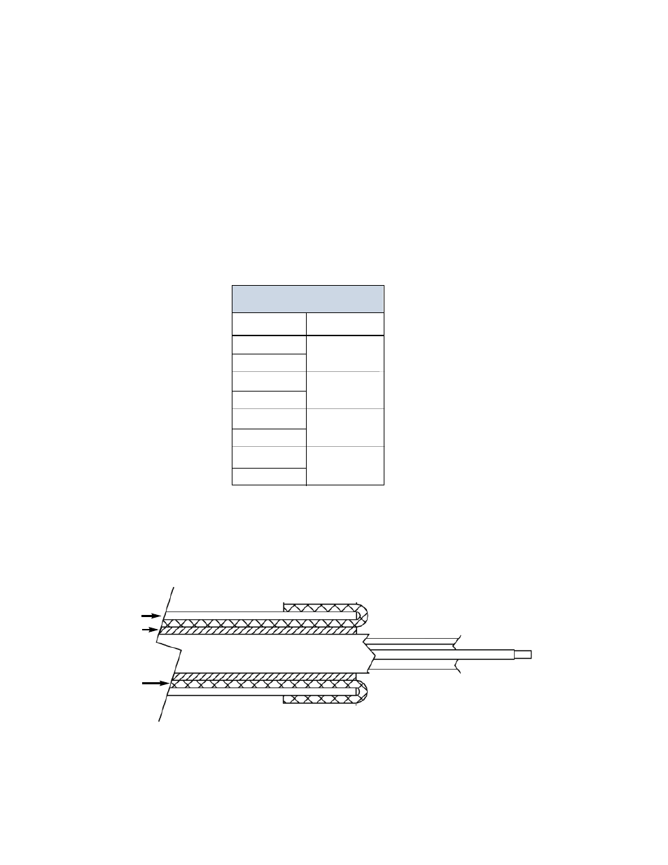
Fold braided shield back over jacket. Example shows double-shielded cable.
Dimensions shown are for illustration only.
Jacket
Aluminum
Polyester
Shied
Braided
Shield
3. Shield Termination:
The customer's cable shield should be in 360° contact with the connector shroud and the connector shell to
provide complete shielding. The connector shell should be metal with conductive surfaces. Suggested metal
connector shells for use with MTE
™
encoders: AMP 748676-1 or equivalent. The shield should be terminated
as illustrated in the following diagram.
2. Signal Wiring
Each differential signal should be connected to a corresponding twisted pair as follows: