Appendix b - wiring diagrams, Wiring diagrams, Appendix b – MicroE MTE Series User Manual
Page 14: Connector pin configuration, Grounding considerations, Recommended signal termination, Page 14
Page 14
Appendix B
Wiring Diagrams
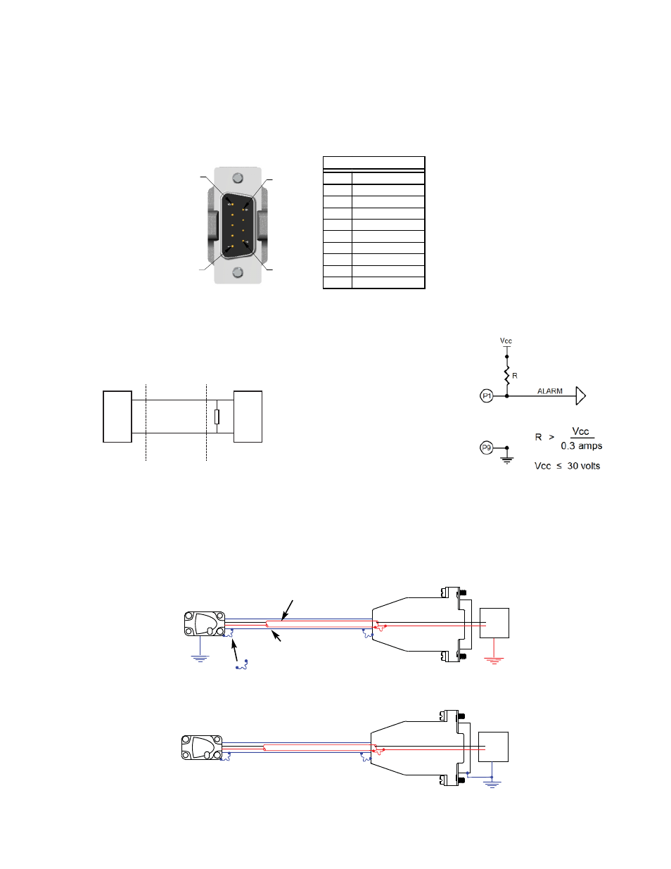
Connector Pin Configuration
Electrically conductive mechanical
connection (as supplied by MicroE
Systems).
INNER SHIELD:
Insulated from outer shield, sensor case, and
connector housing. Connected to circuit common
internally as supplied by MicroE Systems
OUTER SHIELD: Connected to
sensor and connector housing
Grounding Considerations
Sensor mounted with good electrical contact to well grounded surface (preferred):
Sensor mounted to poorly grounded or non-conducting surface:
NOTE: GND and INNER SHIELD ARE INTERNALLY CONNECTED.
Max cable length: 5m. Contact MicroE Applications Engineering if longer length required.
Recommended Signal Termination
Cable Zo=
120
Ω
MTE Series
Encoder
Customer
Electronics
120
Ω
+
−
Digital Outputs:
A, B, I
A, B, I
Standard RS-422 Line Receiver Circuitry
PIN 9
PIN 1
PIN 6
PIN 5
$
#"!
#
#
"
5 Volts
0 Volts
Power
Supply
5 Volts
0 Volts
POWER
SUPPLY
5 Volts
0 Volts
Power
Supply
5 Volts
0 Volts
POWER
SUPPLY
Alarm output is an open drain,
N-channel MOSFET. Drain cir-
cuit is normally closed (current
flows) and opens when the
encoder signal is too low. Alarm
requires the use of an external
pull-up resistor. See customer
supplied circuit example on right.
Alarm circuit
Alarm: