Sensor head alignment (side mount configuration), Sensor, Lignment – MicroE MTE Series User Manual
Page 12: Sensor head alignment, Side mount configuration), Series encoders 1
Page 12
Sensor Head Alignment
(Side Mount Configuration)
MTE
™
Series Encoders
1.
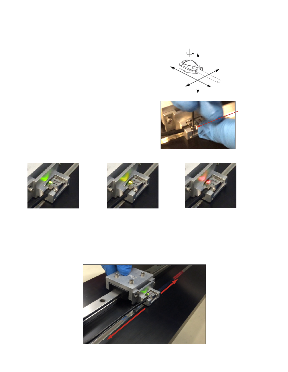
Proper sensor alignment may require minor
adjustments to the sensor position with respect to the
scale. This can be performed easily using the sensor’s
LED indicator.
The red, yellow, or green Signal LEDs will light
depending on sensor alignment. Optimal alignment will
be displayed as a “bright green” Signal LED.
Confirm that the green Signal LED blinks when
passing over the index. If not, readjust the sensor in
the Y-direction and repeat the above procedure.
When alignment is completed, tighten the sensor
mounting screws (0.37Nm [3.3 inch-lbs.] maximum
torque).
2.
Confirm that the Signal LED remains green over the full range of motion by sliding the scale past the
sensor. The green Signal LED must remain on over the entire range. If not aligned over the entire
range of motion, loosen the sensor mounting screws and repeat step 1.
The LED should blink when passing the index mark.
Z
Y
X
θ
z
Green:
Optimal
Performance
Yellow:
Marginal
Performance
Red:
Improper
Performance
Loosen the
sensor mounting
screws/washers
to reposition the
sensor in the
Y-axis if needed.