Dometic BRISK AIR 590 SERIES User Manual
Page 9
9
INSTALLATION INSTRUCTIONS
TROL KIT
A. If your installation included the optional electric heat kit,
install it at this time. Follow the instructions with the
heat package for its installation procedure.
B. Terminate the 4-conductor control cable(s) protruding
into the 4-/4” x 4-/4” (±/8”) roof opening. The
cable(s) must be terminated with an RJ--4C-6P telephone
connector. Refer to the crimp tool manufacture for
crimping instructions.
Important:
RJ-11-4C-6P connectors must be installed as shown
in FIg. 4A.
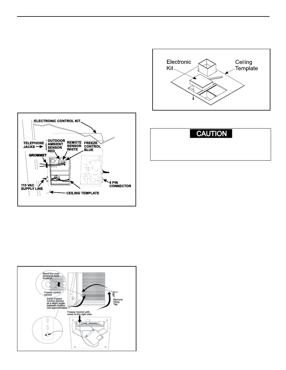
C. Remove the junction box cover from the Electronic
Control Kit. See FIG. .
D. Plug the electrical conduit (6-pin connector) from the
upper unit into the mating connector in Electronic Con-
trol Kit. See FIG. .
E. Plug the control cable(s) into the telephone jack(s) on
the Electronic Control Kit. (It does not matter which
one.)
F. Route the Remote Temperature Sensor cable, if appli-
cable, through the same round grommet where freeze
control wires go into the Electronic Box. See FIG. .
Connect it to the connector that matches its color.
g. Insert the Freeze Control Sensor approximately ” into
the evaporator coil fins as shown in FIG. 12.
H. Locate the electronic control kit on the ceiling template
as shown in FIG. 3. Drive two (2) #0 x 3/8” blunt point
phillips head screws (provided) through ceiling template
into holes in electronic control kit to hold it in place.
8. WIRINg OF SySTEM
A. CONNECTION OF LOW VOLTAgE WIRES
Disconnect the positive (+) 12 volt DC terminal at the
supply battery. Damage to equipment could occur if
the 12 volt DC is not shut off.
. Connect the previously run 2 VDC to the red and
black wires protruding from the Electronic Control Kit.
(In multiple zone installations, this needs to be done
at only one zone.) Connect +2 VDC to the red wire;
-2 VDC to the black wire.
2. Connect the previously run furnace thermostat wires
(if applicable) to the blue wires protruding from the
electronic Control Kit. The polarity of these connec-
tions does not matter. If not used, terminate wire with
twist connector.
3. Connect the previously run Energy Management
System wires (if applicable) to the yellow wires
protruding from the Electronic Control Kit. The
polarity of these connections does not matter. If not
used, terminate wire with twist connector.
FIg. 11
FIg. 12
FIg. 13