beautypg.com
2
INSTALLATION INSTRUCTIONS
AIR CONDITIONINg UNIT
A. (4) /4” — #20 x 7” bolts
B. (4) #8 x 5/8” long sharp point wood screws
C. (7) #0 x 3/8” blunt point tapping screws
D. () Hole Plug
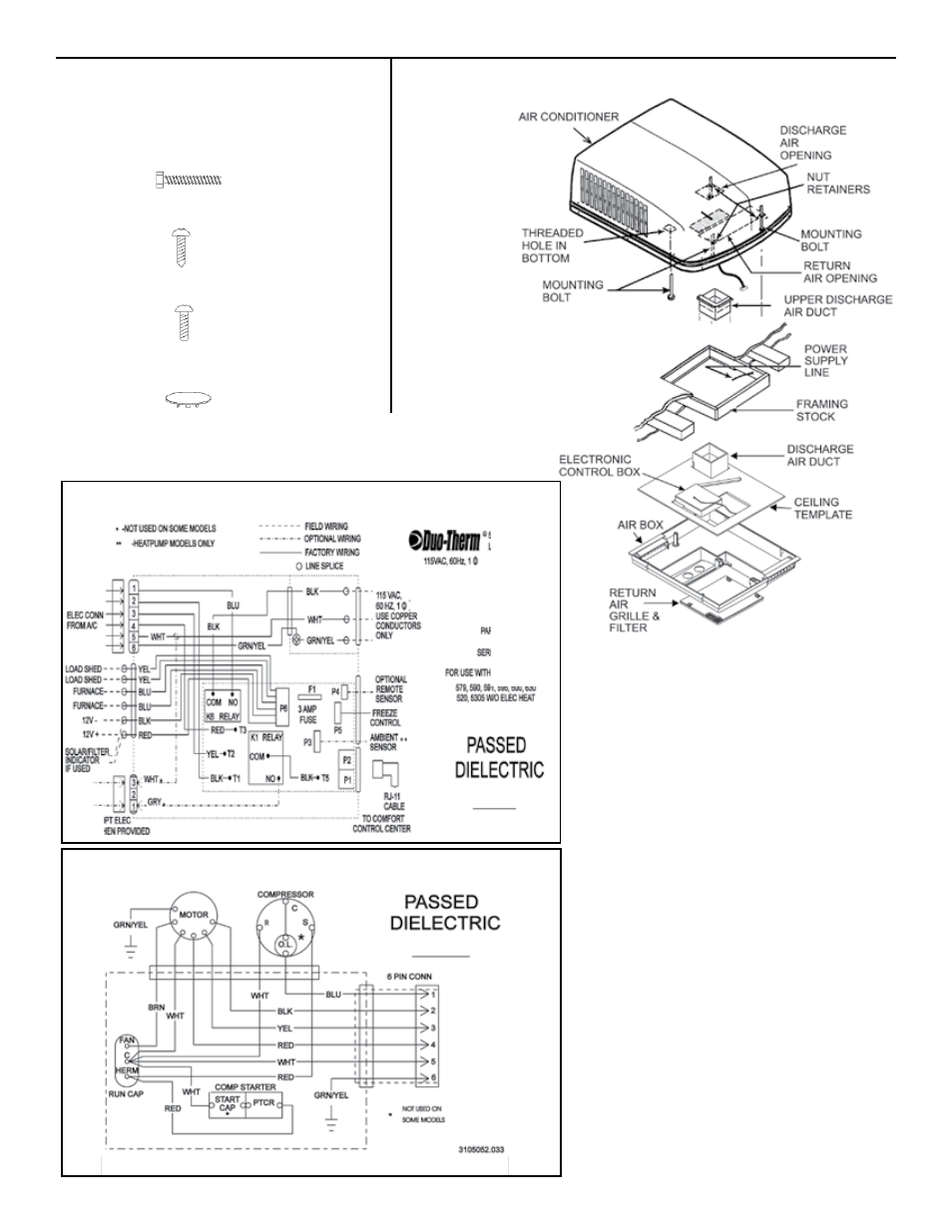
MOUNTINg PARTS
ELECTRONIC CONTROL KIT
UNIT FIELD WIRINg DIAgRAM