Discharge duct & ceiling template installation – Dometic BRISK AIR 590 SERIES User Manual
Page 8
8
INSTALLATION INSTRUCTIONS
6. DISCHARgE DUCT & CEILINg
TEMPLATE INSTALLATION
A. Remove the air box and mounting hardware from their
carton. The upper duct is shipped inside the lower duct
which is part of the ceiling template.
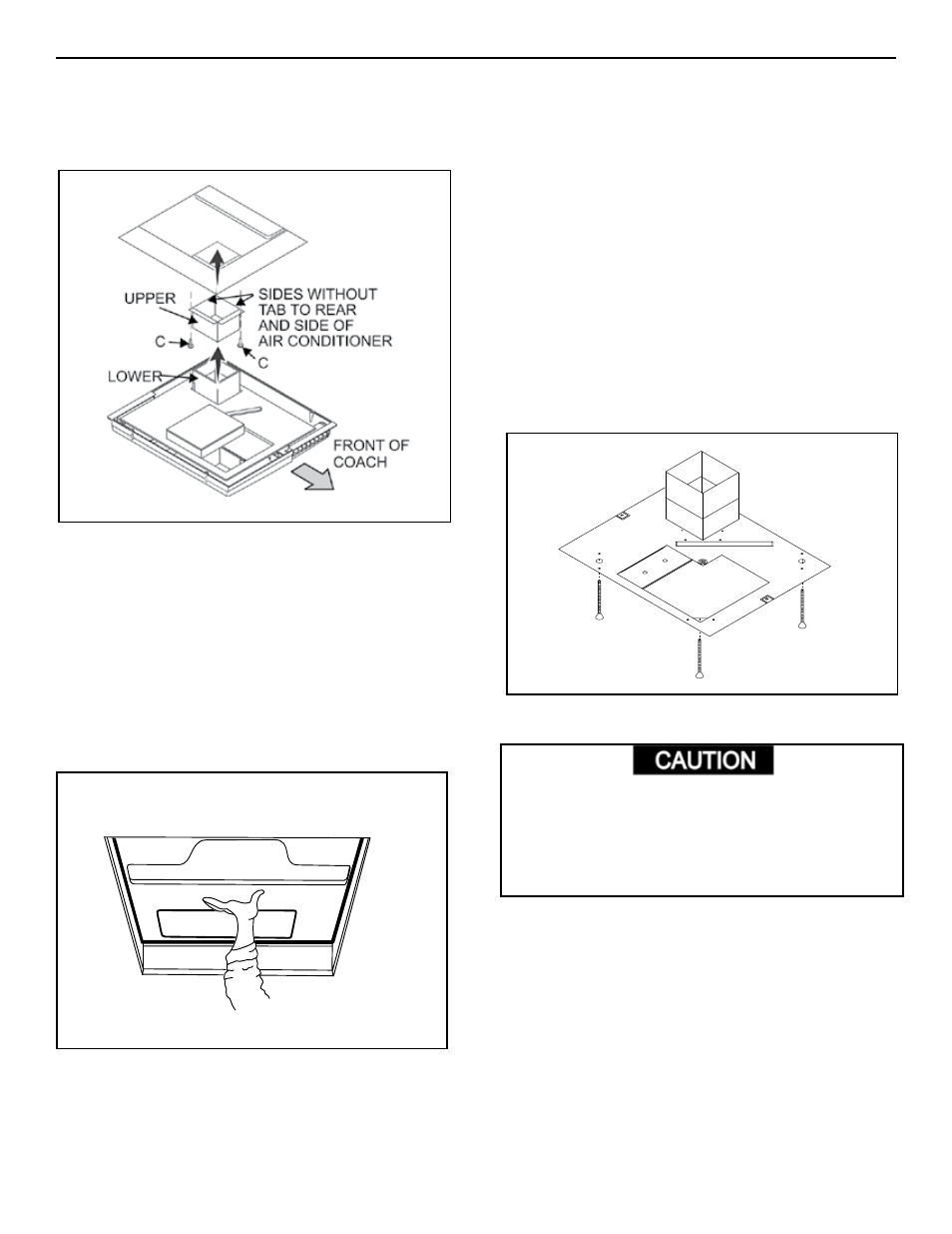
B. Remove the upper duct from the ceiling template and
locate it over the blower discharge.
Note: The edge without the flange installs toward the rear
and side of the opening.
C. Use two of the sharp pointed sheet metal screws to hold
the duct to the base pan. The holes are pre-punched in
the pan for each location.
D. Check gasket alignment over roof opening and adjust if
necessary (roof gasket centers over opening). Unit may
be moved from below by lifting and sliding.
E. Reach up into the return air opening and pull the conduit
power cable down for later connection. See FIG. 9.
FIg. 8
F. Measure the ceiling thickness:
. If the distance is 2” to 3” remove the perforated tabs
from the bottom duct only.
2. If the distance is 3” to 4” install ducts as received.
3. If the distance is 4” to 6” (maximum thickness),
optional Duct Kit and Bolt Kit are available:
Duct Kit (Part No. 306775.004)
Bolt Kit (Part No. 300895.006)
g. Take the ceiling template and slide the lower unit over the
upper duct.
H. Hold the ceiling template with one hand and with the
other, install the four /4” mounting bolts through the
template and into the base pan. See FIG. 0.
. Finger-tighten the four (4) bolts and check alignment.
There should be an equal opening on each side and
the rear flange must be tight against the roof opening.
2. EVENLy tighten the bolts to a torque of 40 to 50 inch
pounds. This will compress the roof gasket to ap-
proximately /2”.
If bolts are left loose there may not be an adequate roof
seal or if over tightened, damage may occur to the air
conditioner base or ceiling template. Tighten to torque
specifications listed in this manual.
7. INSTALLATION OF ELECTRONIC CON-
FIg. 10
Note: In some applications it may be necessary to extend
the 6 pin cable. Order cable number 305584.00 if needed.
FIg. 9
Center Unit From Below