The front panel layout, Led pl time, Led ref time – Meinberg FDM509 User Manual
Page 6: Led overflow, Led fail, Push button reset
6
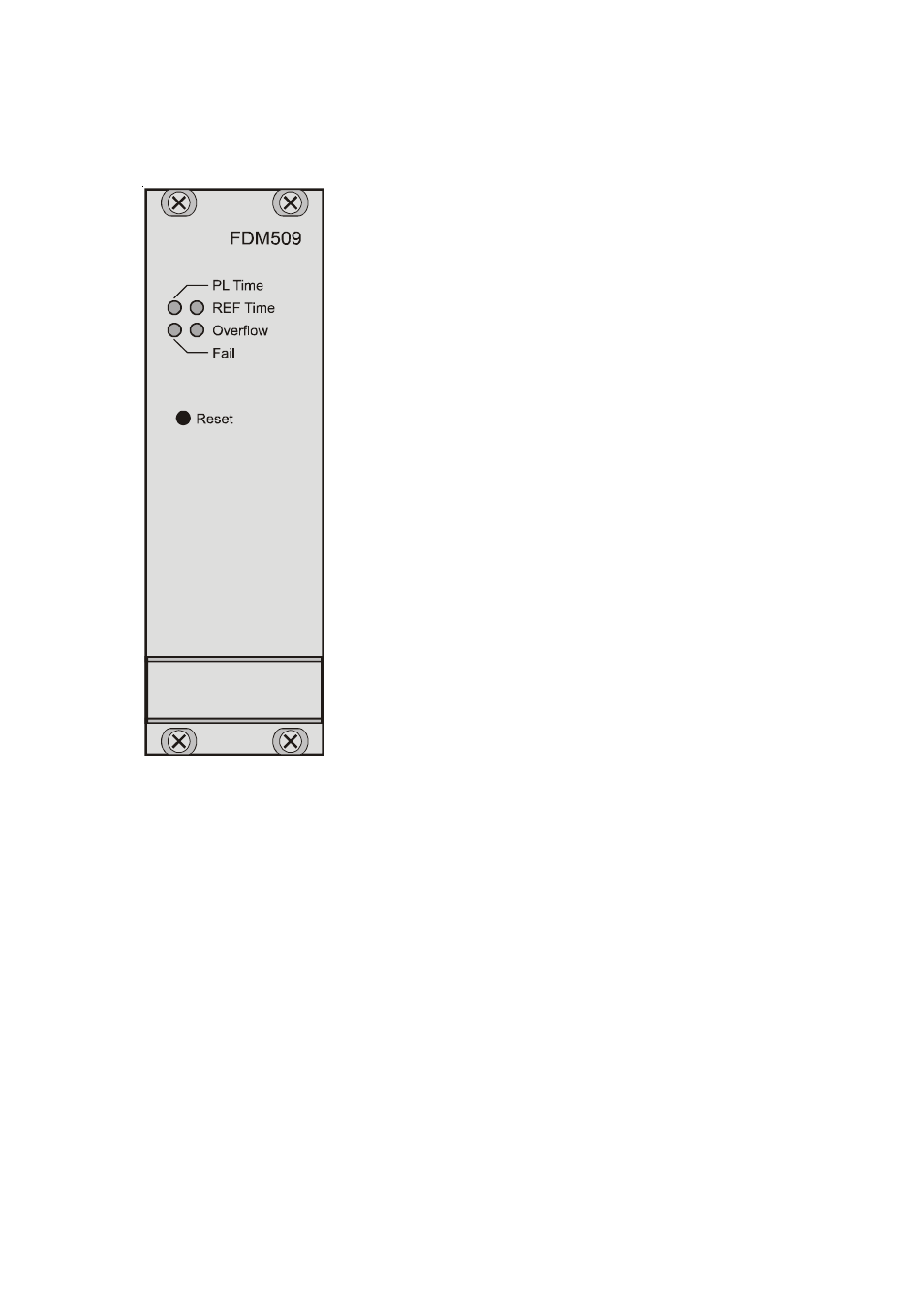
The Front Panel Layout
The 40.6mm wide front panel integrates four LED
indicators and a covered push button.
LED PL Time
This LED toggles once per second corresponding to
the power line time seconds when the mains frequen-
cy is detected correctly. It stops toggling if either the
mains frequency or the 10MHz reference is not app-
lied or the REF time could not be read out after reset.
LED REF Time
This LED toggles once per second corresponding to
the pulse per second of the reference. It stops togg-
ling if either the PPS or the 10MHz reference is not
applied or the REF time could not be read out after
reset.
LED Overflow
This LED is switched on when the time deviation
(the difference between REF time and PL time) ex-
ceeds the limit of ±100 seconds. It is switched off
again when either the time deviation is dropped be-
low ±100 seconds or a reset sets the time deviation
back to zero.
LED Fail
This LED is switched on if correct operation of the module is not ensured and the
results are unusable. Loosing the PPS or the 10MHz from the referenc could be a
reason for this as well as an error in reading in the REF time. The serial output of the
measure string is stopped when this LED is switched on.
Push Button Reset
The time deviation is set to zero if this covered key is pressed for one second at least.
Furthermore the PL time is initialized with the REF time, provided that a time string is
applied to the serial port COM1 and the corresponding DIP switch is set. If not, both
the PL time and the REF time are set to 00:00:00. Also all error bits are cleared and the
analog outputs are set to their initial state (0V). Pressing the reset key has the same
effect than causing a hardware power-up reset or sending a serial reset command.