Measurement Computing PCI-DAS64/M2/16 User Manual
Page 16
PCI-DAS64/M2/16 User's Guide
Installing the PCI-DAS64/M2/16
37
19
20
1
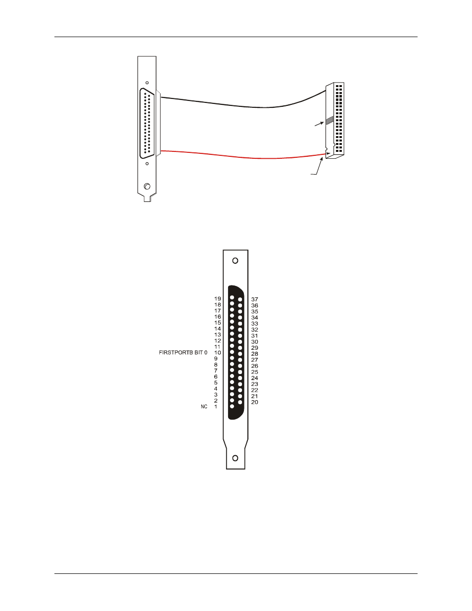
The red stripe and arrow
identify pin # 1
2
40
1
39
Key
37-pin Male D Connector
with Backplate Assembly
40-pin Female
IDC Connector
Figure 2-5. BP40-37 cable
+5V
GND
FIRSTPORTC BIT 7
FIRSTPORTC BIT 6
FIRSTPORTC BIT 5
FIRSTPORTC BIT 4
FIRSTPORTC BIT 3
FIRSTPORTC BIT 2
FIRSTPORTC BIT 1
FIRSTPORTC BIT 0
FIRSTPORTA BIT 7
FIRSTPORTA BIT 6
FIRSTPORTA BIT 4
FIRSTPORTA BIT 3
FIRSTPORTA BIT 2
FIRSTPORTA BIT 1
FIRSTPORTA BIT 0
FIRSTPORTB BIT 2
FIRSTPORTB BIT 3
FIRSTPORTB BIT 4
FIRSTPORTB BIT 5
FIRSTPORTB BIT 6
FIRSTPORTB BIT 7
NC
FIRSTPORTB BIT 1
GND
NC
GND
NC
GND
NC
GND
GND
+5V
FIRSTPORTA BIT 5
Figure 2-6. BP40-37 cable pin out
2-8
This manual is related to the following products: