Measurement Computing PCM-D24/CTR3 rev.3 User Manual
Page 19
MS = Mode Set. 1 = mode set active
M3
M2
Group A Function
0
0
Mode 0 Input / Output
0
1
Mode 1 Strobed Input / Output
1
X
Mode 2 Bi-Directional Bus
A
B
CL
CH
Independent Function
1
1
1
1
Input
0
0
0
0
Output
M1 = 0 is mode 0 for group B. Input / Output
M1 = 1 is mode 1 for group B. Strobed Input / Output
The Ports A, B, C High and C Low may be independently programmed for input or
output.
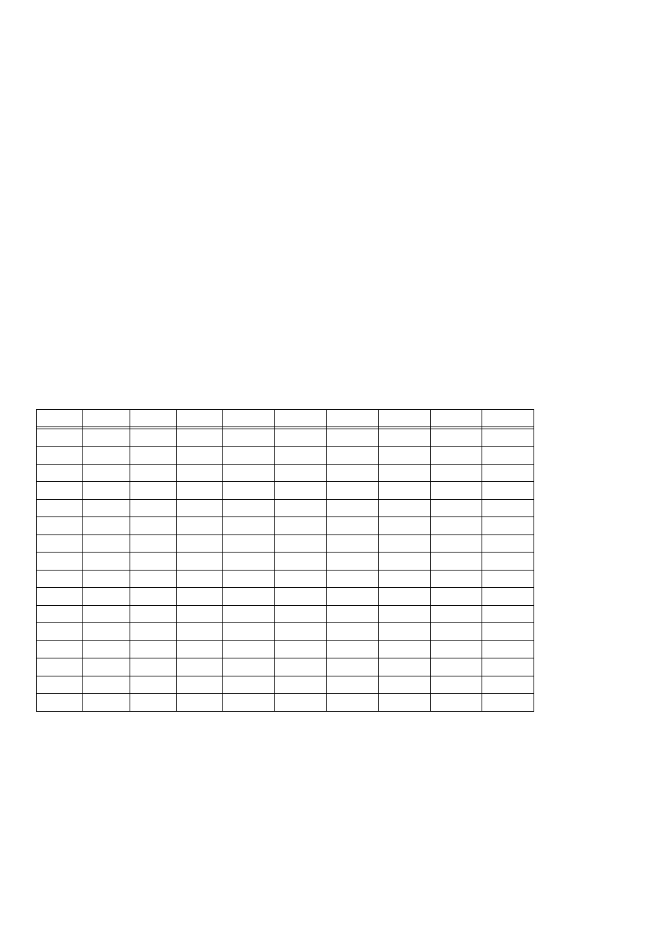
The two groups of ports, group A and group B, may be independently programmed in
one of several modes. The most commonly used mode is mode 0, input / output
mode. The codes for programming the 82C55 in this mode are shown below. D7 is
always 1 and D6, D5 & D2 are always 0.
IN
IN
IN
IN
155
9B
1
1
1
1
OUT
IN
IN
IN
154
9A
0
1
1
1
IN
OUT
IN
IN
153
99
1
0
1
1
OUT
OUT
IN
IN
152
98
0
0
1
1
IN
IN
OUT
IN
147
93
1
1
0
1
OUT
IN
OUT
IN
146
92
0
1
0
1
IN
OUT
OUT
IN
145
91
1
0
0
1
OUT
OUT
OUT
IN
144
90
0
0
0
1
IN
IN
IN
OUT
139
8B
1
1
1
0
OUT
IN
IN
OUT
138
8A
0
1
1
0
IN
OUT
IN
OUT
137
89
1
0
1
0
OUT
OUT
IN
OUT
136
88
0
0
1
0
IN
IN
OUT
OUT
131
83
1
1
0
0
OUT
IN
OUT
OUT
130
82
0
1
0
0
IN
OUT
OUT
OUT
129
81
1
0
0
0
OUT
OUT
OUT
OUT
128
80
0
0
0
0
CL
B
CU
A
DEC
HEX
D0
D1
D3
D4
BASE +4, 5, 6, and 7
The 82C54 counter chip is quite complex. The data sheet for the part contains pro-
gramming information, input and output timing diagrams and interfacing specifica-
tions. We are sorry, but it is beyond the scope of this manual to reproduce the
16