Measurement Computing PCM-D24/CTR3 rev.3 User Manual
Page 18
BASE + 2 82C55 Port C
The direction of this port is set by writing a control word to BASE + 3. The port is
byte wide but may be configured in 4 bit nibbles. It may be set as 8 in, 8 out, or split
to 4 in and 4 out. Data is written to and read from this port in bytes even when split as
4&4. The rules for writing and reading data apply regardless of 8 or 4&4 operation.
If programmed for output, a write to this register will update the outputs. A 0 sets the
output to TTL Low. A 1 sets the output to TTL High. NOTE: TTL High is not nec-
essarily 5V. The current high/low bit settings may be read back from the port by read-
ing it.
If programmed for input, a read will capture the current state of all 8 input lines (8
bits) of the port. Writing to an input port has no function.
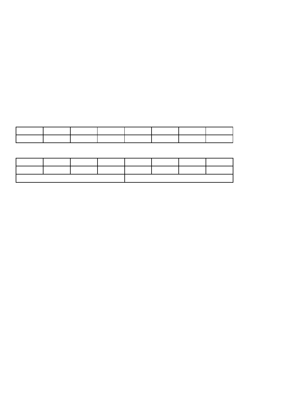
CL0
CL1
CL2
CL3
CH4
CH5
CH6
CH7
0
1
2
3
4
5
6
7
BASE ADDRESS + 3 82C55 CONTROL REGISTER
Group B
Group A
CL
B
M1
CU
A
M2
M3
MS
0
1
2
3
4
5
6
7
The 82C55 may be programmed to operate in Input/ Output (mode 0), Strobed Input/
Output (mode 1) or Bi-Directional Bus (mode 2).
Included here is information on programming the 82C55 in mode 0. Those wishing to
use the 82C55 in modes 1 or 2, or who wish to program the 82C54 counter on the
PCM-D24/CTR3, must procure a data book from Intel Corporation Literature Depart-
ment. Please check Intel's web site at www.intel.com for more information.
When the PC is powered up or RESET, the 82C55 is reset. This places all 24 lines in
Input mode and no further programming is needed to use the 24 lines as TTL
inputs.To program the 82C55 for other modes, the following control code byte must
be assembled into an 8 bit byte.
15