Internal configuration – Measurement Computing TempBook rev.4.0 User Manual
Page 21
TempBook User’s Manual
04-25-01
Installation, Configuration, and Calibration 2-3
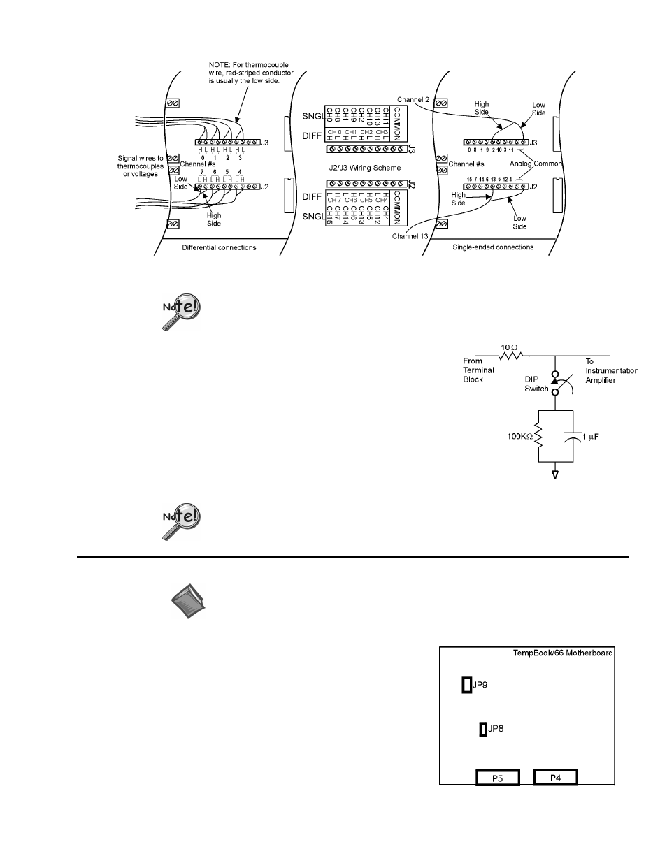
The thermocouple or voltage connections should be made as shown in the following figure.
Analog Signal Connection
When connecting both low and high level signals, the low-level signals should be
connected to the lowest numbered channels with connections following in ascending
order of signal magnitude.
Each of the 16 analog input channels is configured as shown in the
figure (also, refer to
for more information on wiring
differential inputs).
The series resistance and shunt capacitance form a single-pole low-
pass filter with a corner frequency of 15.9 kHz. The shunt
resistance provides the bias current path for the instrumentation
amplifier.
When reading thermocouples, these filters should be switched in.
If the filters are not used with thermocouples or any other
differential input, then the user must provide a bias current return
path to signal common.
Two DIP switches need to be set for each differential channel.
Internal Configuration
Reference Note:
This section pertains to TempBook/66 hardware configuration. Software installation and
software configuration under Windows 95/98/Me/NT and 2000 is discussed in
To open the unit, place the TempBook on a flat surface.
Remove the screw on the top rear of the case, and slide out the
top cover. Reverse this procedure to assemble the unit.
The internal configuration of a TempBook/66 consists of
setting the following jumpers to reflect the desired mode of
operation:
• Time Base (JP9)
• Watchdog Timer Enable (JP8)
The location of each jumper is shown in the figure.