Hardware setup, Card connection – Measurement Computing DBK81 User Manual
Page 2
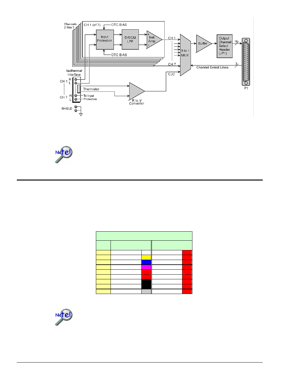
DBK81 Block Diagram*
*The DBK81 block diagram can be applied to the DBK82 and DBK83, as their diagrams only differ to the
one above in regard to the number of input channels provided.
In comparison to other DBK cards, the DBK81, DBK82, and DBK83 demand significant
power from the system’s
±15V power supplies. It is important that you calculate your
system’s power demand, as you may need to add auxiliary power supplies.
Refer to Power Requirements in the DBK Basics section for additional information.
Hardware Setup
Card Connection
Connect the thermocouple wires to the intended input terminals on the card. The DBK81 provides input
connections for channels 1 through 7, while the DBK82 and DBK83 offer input connections for channels
1 through 7 and 9 through 15. All channels have the same level of functionality.
Thermocouple wire is standardized, color-coded, and polarized, as noted in the following table.
Thermocouple Standards
T/C
Type
(+) Lead to
Channel High
(-) Lead to
Channel Low
J White Red
K Yellow Red
T Blue Red
E Violet Red
N28 Orange Red
N14 Orange Red
S Black
Red
R Black
Red
B Gray Red
Input connections for the three cards are labeled “H” and “L” to denote polarity.
For isothermal performance, an exposed, grounded copper plane surrounds the input
connectors. It is important that non-insulated input wires do not contact the grounded
plane
− since such contact can degrade measurement integrity.
pg. 2, DBK81, DBK82, & DBK83
989494
DBK Option Cards and Modules