Dbk40 - specifications – Measurement Computing DBK40 User Manual
Page 3
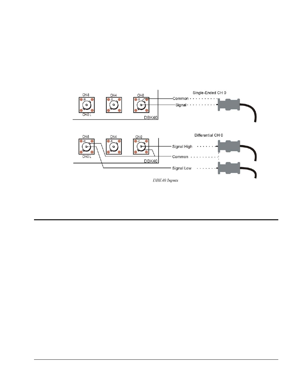
Connect your analog signals to the unit as you would to any other BNC connector. The outer shell is
ground; the center pin is the signal.
The figure below shows connections for single-ended and differential inputs. In the differential mode,
channels 0 to 7 are high; 8 to 15 are low (0 & 8, 1 & 9, 2 &10, etc).
DBK40 - Specifications
Name/Function: BNC Analog Interface Module
Connection: Male DB37 mates with P1.
Analog Input Connection: One BNC connector for each of 16 analog input channels.
Single-Ended Mode: Center conductor carries signal, outer conductor carries signal ground.
Differential Mode: Center conductor of two adjacent BNC connectors carries high and low input signals; the
outer conductors of both are attached to system ground.
Analog Output Connection: One BNC connector for each of 2 analog output channels;
center conductor carries signal, outer conductor carries signal ground.
TTL Trigger Input Connection: One analog output BNC connector can be switched to provide a TTL trigger
input connection; in TTL mode, the second analog output channel is unavailable on the BNC
connector.
Size: 6.8" wide × 5.3" long × 2.3" high
Weight: 21 oz
Length of Supplied Cable: 6 ft
DBK Option Cards and Modules
879795
DBK40, pg. 3