Hardware setup, Using the dbk40, Caution – Measurement Computing DBK40 User Manual
Page 2
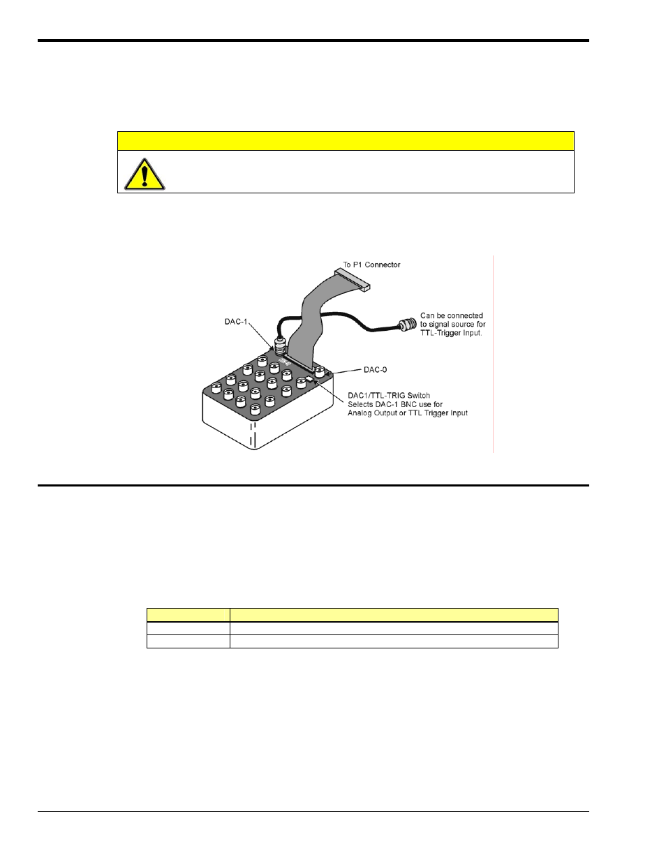
Hardware Setup
The DBK40 has a male DB37 connector that is pin-compatible with the P1 port. Typically a 6-foot ribbon
cable is provided to attach the DBK40 to the P1 connector of the primary acquisition device, e.g., a
LogBook or DaqBook.
CAUTION
Connecting the DBK40 to a port other than P1 may result in damage to the system.
Connect one end of the ribbon cable to the DB37 connector of the DBK40 and the cable's other end to the
Analog I/O Port (P1) of the primary data acquisition device.
Using the DBK40
The DBK40 is equipped with BNC connectors for 16 single-ended or 8 differential inputs. Also provided
are BNC terminals for DAC0 and DAC1 analog outputs.
The DAC-1 connector may be used for access to the LogBook or Daq Device Analog I/O TTL trigger
input. The position of the DBK40 slide switch determines the use of DAC-1, as indicated in the following
table. Verify that this switch is in the correct position for your application.
Switch Setting
Description
TTL/TRIG
Allows the connector to be used for TTL trigger input.
DAC-1
Allows the connector to be used DAC-1 output.
The collars of all of the BNC connectors are common to each other and analog ground. When the TTL
trigger input is selected (via the slide switch), the isolated ground plane of the TTL-TRG/DAC1 connector
is referenced to digital or TTL ground. Most of the top area of the DBK40’s PC board is ground plane that
provides excellent low-impedance, low-noise signal interfacing.
DBK40, pg. 2
879795
DBK Option Cards and Modules