Measurement Computing DBK40 User Manual
Dbk40, Connector bnc analog interface, Overview
DBK40
18- Connector BNC Analog Interface
Overview …… 1
Hardware Setup …… 2
Using the DBK40 …… 2
DBK40 – Specifications …… 3
Reference Notes:
o
Chapter 2 includes pinouts for P1, P2, P3, and P4. Refer to pinouts applicable to your
system, as needed.
o
In regard to calculating system power requirements, refer to DBK Basics located near
the front of this manual.
Overview
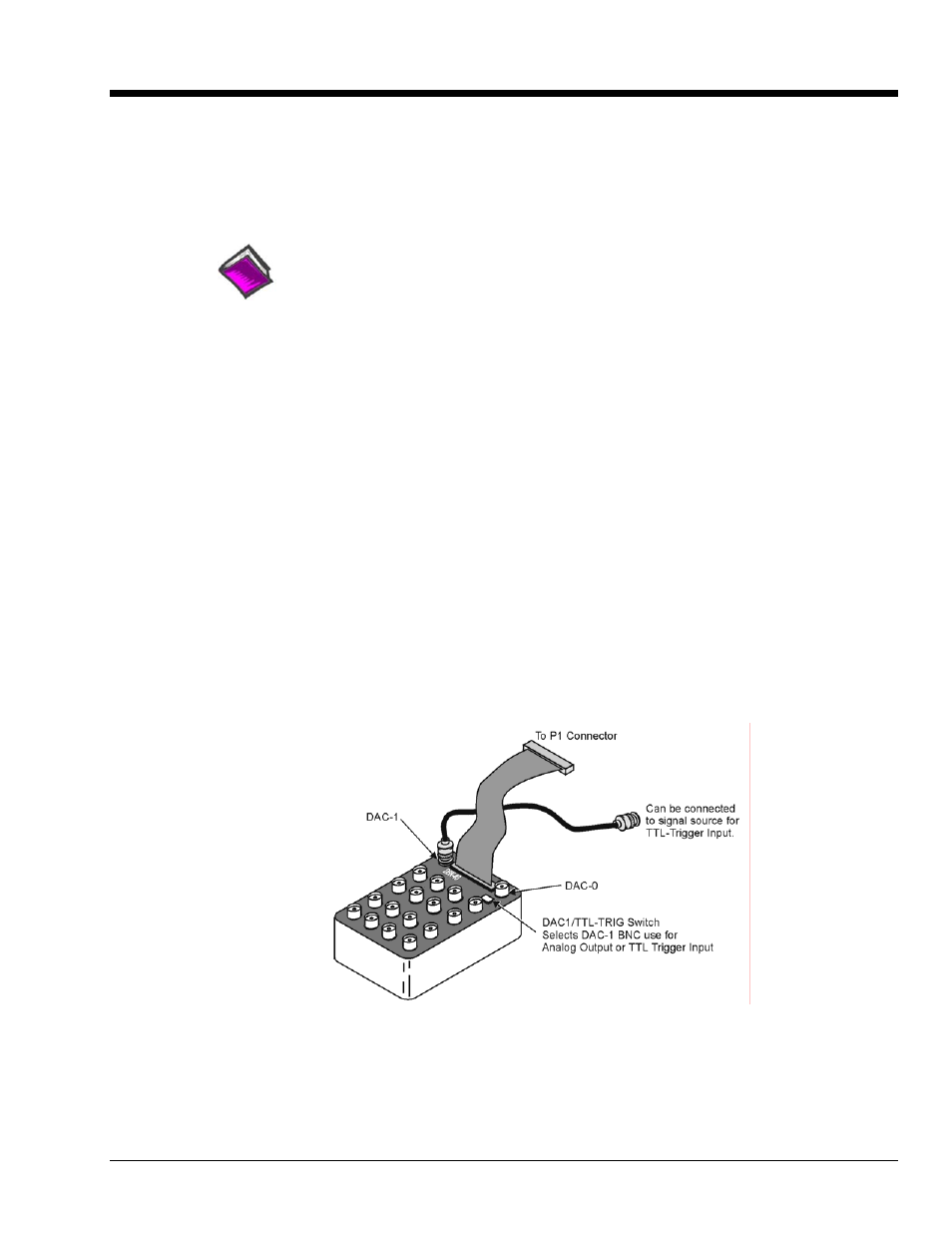
The DBK40 is a termination panel consisting of 18 BNC connectors. The unit provides an easy means of
attaching analog signals from BNC cables to a to a DB-37 connector, such as P1 on a LogBook, a Daq
device, or a DBK module.
The panel includes:
•
16 analog input channels
•
2 analog output channels (DAC-0 and DAC-1)
•
a slide switch (DAC1/TTL-TRIG Switch)
•
a male DB37 connector
The DAC1/TTL-TRIG Switch is used to select the mode of the DAC-1 BNC connector. DAC-1 can be
used as an analog output channel, or as a TTL Trigger Input.
DBK40
DBK Option Cards and Modules
879795
DBK40, pg. 1