Digital input/output, Temperature alarms, Memory – Measurement Computing WLS-TC User Manual
Page 20
WLS-TC User's Guide
Specifications
20
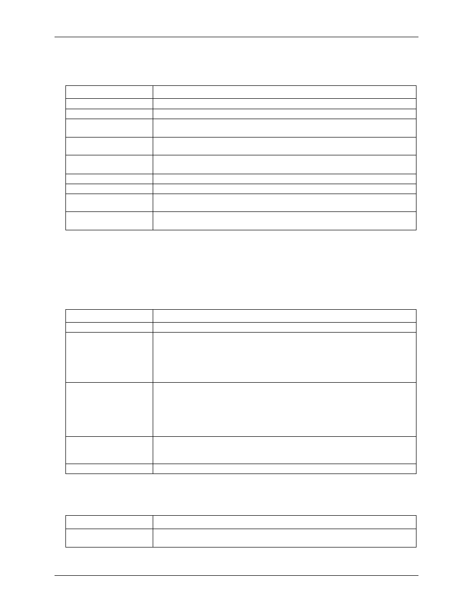
Digital input/output
Table 5. Digital input/output specifications
Parameter
Specification
Digital type
CMOS
Number of I/O
8 (DIO0 through DIO7)
Configuration
Independently configured for input or output.
Power on reset is input mode unless bit is configured for alarm.
Pull up/pull-down
configuration
All pins pulled up to +5 V via 47 K kΩ resistors (default). Pull down to ground (GND)
also available.
Digital I/O transfer rate
(software paced)
Digital input – 50 port reads or single bit reads per second typ
Digital output – 100 port writes or single bit writes per second typ
Input high voltage
2.0 V min, 5.5 V absolute max
Input low voltage
0.8 V max, –0.5 V absolute min
Output low voltage
(IOL = 2.5 mA)
0.7 V max
Output high voltage
(IOH = –2.5 mA)
3.8 V min
Note 7:
All ground pins on the device (pins 9, 19, 28, 38) are isolated from earth ground. If a connection is
made to earth ground when using digital I/O and conductive thermocouples, the thermocouples are no
longer isolated. In this case, thermocouples must not be connected to any conductive surfaces that may
be referenced to earth ground.
Temperature alarms
Table 6. Temperature alarm specifications
Parameter
Specification
Number of alarms
8 (one per digital I/O line)
Alarm functionality
Each alarm controls its associated digital I/O line as an alarm output. The input to each
alarm may be any of the analog temperature input channels. When an alarm is enabled, its
associated I/O line is set to output (after the device is reset) and driven to the appropriate
state determined by the alarm options and input temperature. The alarm configurations are
stored in non-volatile memory and are loaded at power on. Alarms will function both in
wireless mode and while attached to USB.
Alarm input modes
Alarm when input temperature > T1
Alarm when input temperature > T1, reset alarm when input temperature goes below T2
Alarm when input temperature < T1
Alarm when input temperature < T1, reset alarm when input temperature goes above T2
Alarm when input temperature is < T1 or > T2
Note: T1 and T2 may be independently set for each alarm.
Alarm output modes
Disabled, digital I/O line may be used for normal operation
Enabled, active high output (digital I/O line goes high when alarm conditions met)
Enabled, active low output (digital I/O line goes low when alarm conditions met)
Alarm update rate
1 second
Memory
Table 7. Memory specifications
Parameter
Specification
EEPROM
1,024 bytes isolated micro reserved for sensor configuration
256 bytes USB micro for external application use