Ac power supply, External components, Screw terminals – Measurement Computing WLS-TC User Manual
Page 16
WLS-TC User's Guide
Functional Details
16
To reduce the error, reduce the length of the thermocouple to lower its resistance, or lower the AWG of the wire
by using a wire with a larger diameter. With OTD disabled, a maximum of 30 nA of input leakage current is
injected into the thermocouple.
AC power supply
The external power supply is an AC-to-USB 2.5 W supply that is used to power the WLS-TC during remote
wireless operations (MCC p/n USB Power Adapter.)
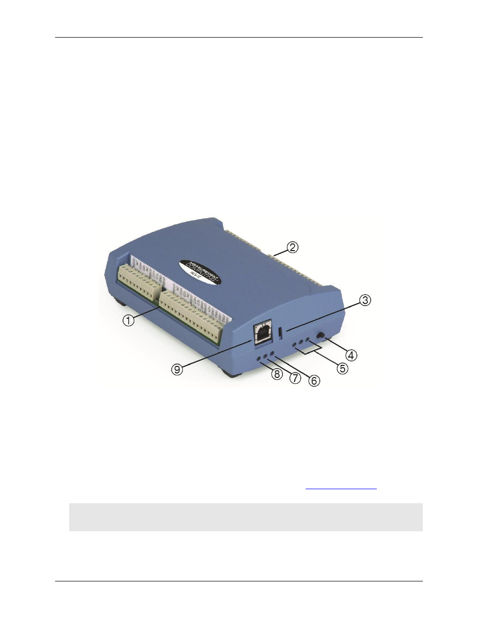
External components
The WLS-TC has the following external components, as shown in Figure 5.
Screw terminals
USB connector
Status LEDs (Command, Wireless Power, Transmit, Receive, Received Signal Strength indicators)
LED Test button
1
Screw terminal pins 1 to 26
6
Receive LED
2
Screw terminal pins 27 to 52
7
Transmit LED
3
Command LED
8
Wireless Power LED
4
LED Test button
9
USB connector
5
Received Signal Strength (RSS) LEDs
Figure 5. WLS-TC component locations
Screw terminals
The device's four banks of screw terminals are for connecting thermocouples and digital I/O lines. These
terminals also provide ground and power output connections. Refer to the "
" section on
page 12 for screw terminal descriptions.
Caution! The two
+5V
terminals (pin 21 and pin 47) are isolated (500 VDC) from the USB +5V. Each +5V
terminal is an output. Do not connect to an external power supply or you may damage the WLS-
TC and possibly the computer.