Functional details, External components, Status leds – Measurement Computing WLS-IFC User Manual
Page 9: Chapter 3
9
Chapter 3
Functional Details
External components
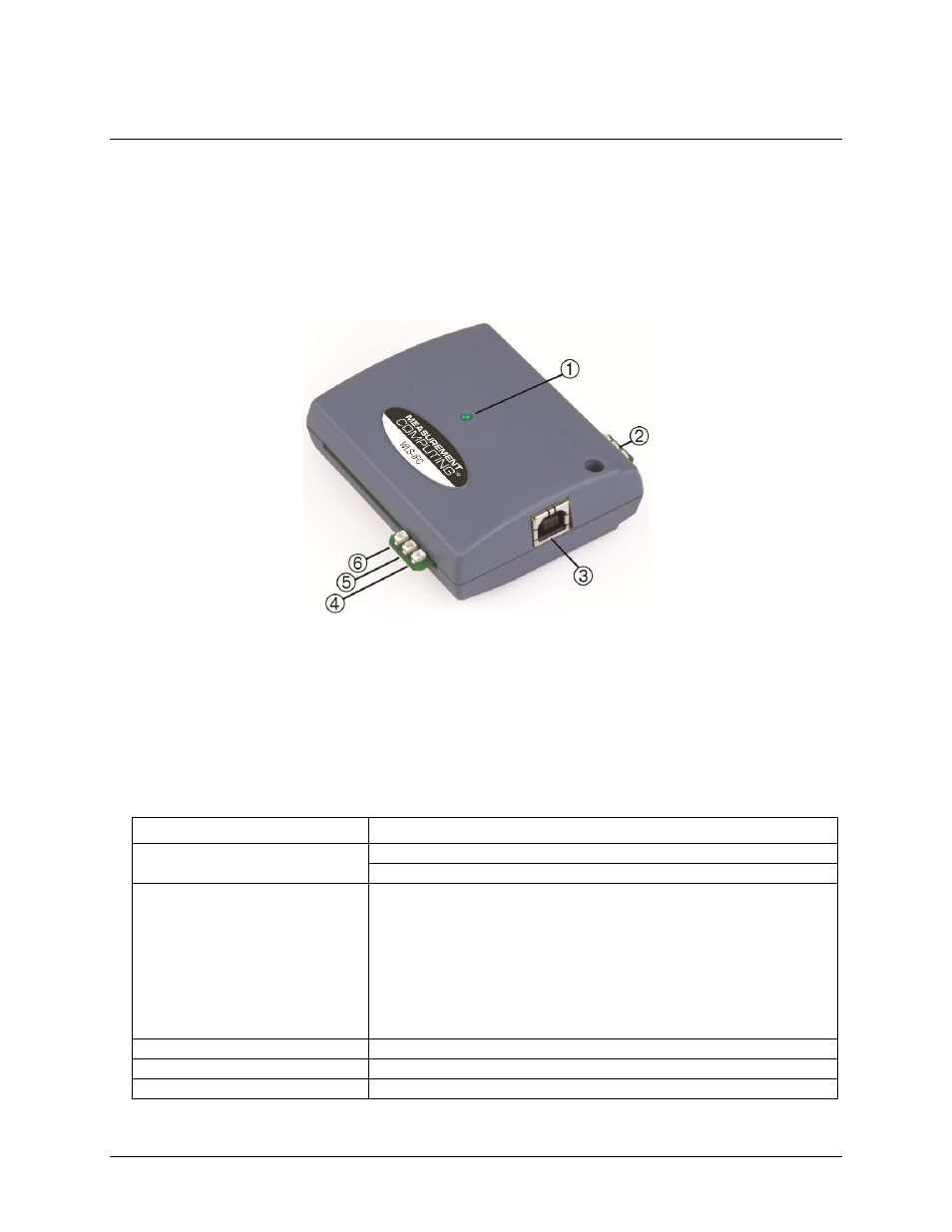
The WLS-IFC has the following external components, as shown in Figure 3.
Status LEDs (USB Activity, Transmit, Receive, Received Signal Strength indicators)
Power LED
USB connector
1
Power LED
4
USB Activity LED
2
Received Signal Strength (RSS) LEDs
5
Transmit LED
3
USB connector
6
Receive LED
Figure 3. WLS-IFC component locations
Status LEDs
The LEDs indicate the communication status of USB and wireless operations. An LED bar graph indicates the
strength of the signal received by the remote device. Refer to the table below for the function of each LED.
LED functions
LED
Function
Power
Steady green – the WLS-IFC is connected to a computer or external USB hub.
Blinking green – indicates activity over the USB connection.
Received Signal Strength (RSS)
indicators
3 green LED bar graph. The LEDs will turn on when receiving a wireless
message and stay on for approximately 1 second after the end of the message.
They indicate the amount of fade margin present in an active wireless link. Fade
margin is defined as the difference between the incoming signal strength and the
device’s receiver sensitivity.
Three LEDs on : Very strong signal (> 30 dB fade margin)
Two LEDs on : Strong signal (> 20 dB fade margin)
One LED on : Moderate signal (> 10 dB fade margin)
No LEDs on: Weak signal (< 10 dB fade margin)
USB activity
Green LED – indicates activity over the USB connection.
Transmit
Yellow LED – indicates transmitting data over the wireless link.
Receive
Red LED – indicates receiving data over the wireless link.