Led configuration – Measurement Computing WLS-IFC User Manual
Page 13
WLS-IFC User's Guide
Specifications
13
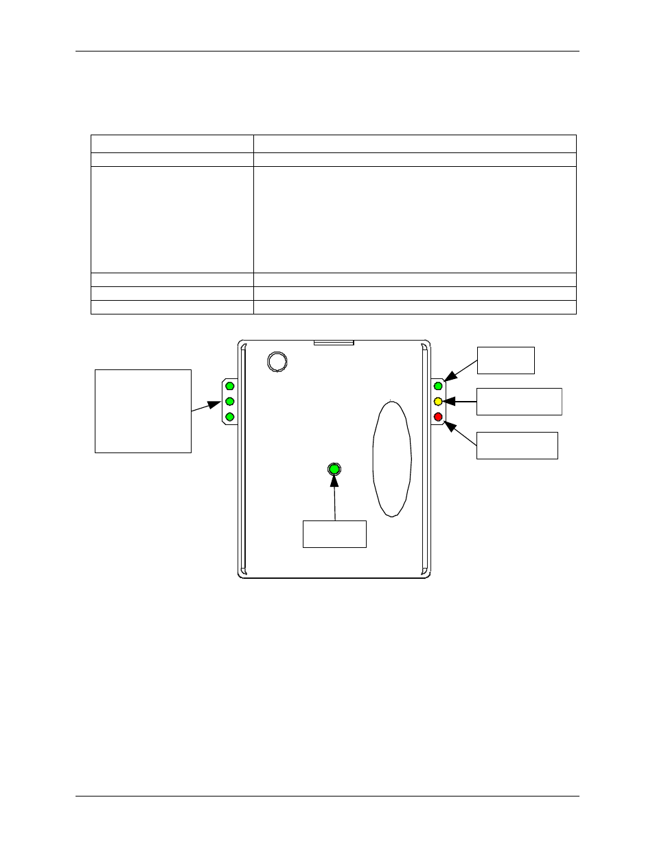
LED configuration
Table 9. LED configuration
Parameter
Specification
Power
The WLS-IFC is connected to a computer or external USB hub
Received Signal Strength Indicator
(RSSI)
3 green LED bar graph. The LEDs will turn on when receiving a wireless
message and stay on for approximately 1 second after the end of the message.
They indicate the amount of fade margin present in an active wireless link. Fade
margin is defined as the difference between the incoming signal strength and the
device's receiver sensitivity.
3 LEDs on: Very strong signal (> 30 dB fade margin)
2 LEDs on: Strong signal (> 20 dB fade margin)
1 LED on: Moderate signal (> 10 dB fade margin)
0 LEDs on: Weak signal (< 10 dB fade margin)
USB activity
Green LED: activity is detected over the USB connection
Transmit
Yellow LED: data is being transmitted over the wireless link.
Receive
Red LED: data is being received over the wireless link.
Power
Received
Signal
Strength
Indicator
USB
Transmit
Receive