Mechanical, Screw terminal connector – Measurement Computing USB-TEMP-AI User Manual
Page 28
USB-TEMP-AI User's Guide
Specifications
28
Mechanical
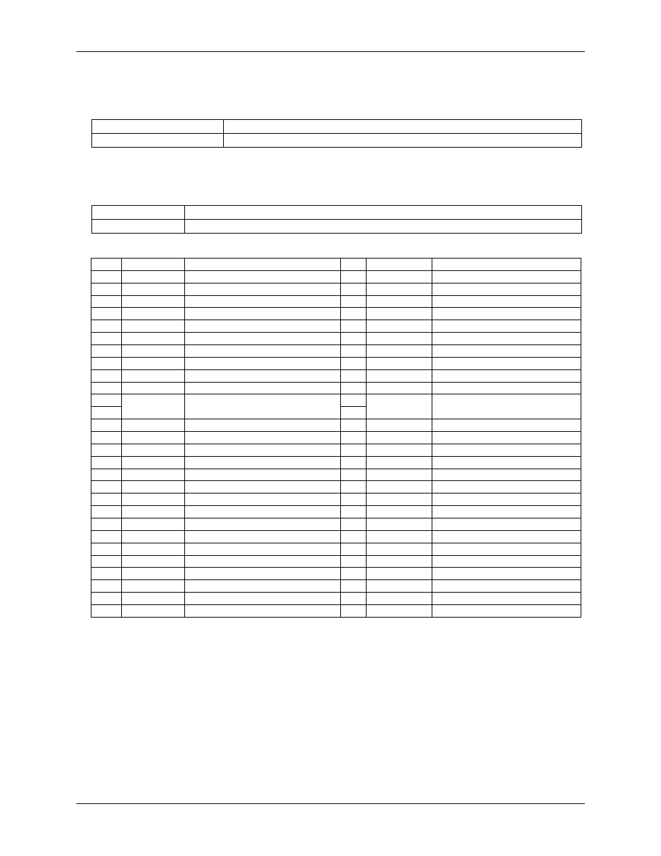
Table 24. Mechanical specifications
Dimensions (L × W × H)
128.52 x 88.39 × 35.56 mm (5.06 × 3.48 × 1.43 ft)
User connection length
3 m (9.84 ft) max
Screw terminal connector
Table 25. Screw terminal connector specifications
Connector type
Screw terminal
Wire gauge range
16 AWG to 30 AWG
Table 26. Screw terminal pinout
Pin
Signal Name
Pin Description
Pin
Signal Name
Pin Description
1
I1+
T0/T1 current excitation source
27
GND
Ground
2
NC
No connection
28
V3L
V3 voltage input (
–)
3
T0H
T0 sensor input (+)
29
V3H
V3 voltage input (+)
4
T0L
T0 sensor input (
–)
30
GND
Ground
5
4W01
T0/T1 4-wire, 2 sensor common
31
V2L
V2 voltage input (
–)
6
IT01
T0/T1 2-sensor common
32
V2H
V2 voltage input (+)
7
T1H
T1 sensor input (+)
33
GND
Ground
8
T1L
T1 sensor input (
–)
34
V1L
V1 voltage input (
–)
9
GND
Ground
35
V1H
V1 voltage input (+)
10
I1
–
T0/T1 current excitation return
36
GND
Ground
CJC sensor
11
I2+
T2/T3 current excitation source
37
V0L
V0 voltage input (
–)
12
NC
38
V0H
V0 voltage input (+)
13
T2H
T2 sensor input (+)
39
GND
Ground
14
T2L
T2 sensor input (
–)
40
CTR
Counter Input
15
4W23
T2/T3 4-wire, 2 sensor common
41
DIO7
DIO channel 7
16
IT23
T2/T3 2 sensor common
42
DIO6
DIO channel 6
17
T3H
T3 sensor input (+)
43
DIO5
DIO channel 5
18
T3L
T3 sensor input (
–)
44
DIO4
DIO channel 4
19
GND
Ground
45
DIO3
DIO channel 3
20
I2
–
T2/T3 current excitation return
46
DIO2
DIO channel 2
21
+5V
+5V output
47
DIO1
DIO channel 1
22
GND
Ground
48
DIO0
DIO channel 0
23
NC
No connection
49
GND
Ground
24
NC
No connection
50
NC
No connection
25
NC
No connection
51
NC
No connection
26
NC
No connection
52
NC
No connection