Rtd and thermistor connections, Two-wire configuration, Two-wire, single-sensor – Measurement Computing USB-TEMP-AI User Manual
Page 13
USB-TEMP-AI User's Guide
Signal I/O Connections
13
RTD and thermistor connections
A resistance temperature detector (RTD) measures temperature by correlating the resistance of the RTD
element with temperature. A thermistor is a thermally-sensitive resistor that is similar to an RTD in that its
resistance changes with temperature — thermistors show a large change in resistance that is proportional to a
small change in temperature. The main difference between RTD and thermistor measurements is the method
used to linearize the sensor data.
RTDs and thermistors are resistive devices that require an excitation current to produce a voltage drop that can
be measured differentially across the sensor. The USB-TEMP-AI features two built-in current excitation
sources (±I1 and ±I2) for measuring resistive type sensors. Each current excitation terminal is dedicated to one
channel pair.
The USB-TEMP-AI makes two, three, and four-wire measurements of RTDs (100 Ω platinum type) and
thermistors.
Use InstaCal to select the sensor type and the wiring configuration. Once the resistance value is calculated, the
value is linearized in order to convert it to a temperature value. A 32-bit floating point value in either
temperature or resistance is returned by software.
RTD maximum resistance
Resistance values greater than 660 Ω cannot be measured by the USB-TEMP-AI in the RTD mode. The 660 Ω
resistance limit includes the total resistance across the current excitation (±Ix) pins, which is the sum of the
RTD resistance and the lead resistances.
Thermistor maximum resistance
Resistance values greater than 180 kΩ cannot be measured by the USB-TEMP-AI in the thermistor mode. The
180 kΩ resistance limit includes the total resistance across the current excitation (±Ix) pins, which is the sum of
the thermistor resistance and the lead resistance.
Two-wire configuration
The easiest way to connect an RTD sensor or thermistor to the USB-TEMP-AI is with a two-wire configuration,
since it requires the fewest connections to the sensor. With this method, the two wires that provide the RTD
sensor with its excitation current also measure the voltage across the sensor.
Since RTDs exhibit a low nominal resistance, measurement accuracy can be affected due to the lead wire
resistance. For example, connecting lead wires that have a resistance of 1 Ω (0.5 Ω each lead) to a 100 Ω
platinum RTD will result in a 1% measurement error.
With a two-wire configuration, you can connect either one sensor per channel pair, or two sensors per channel
pair.
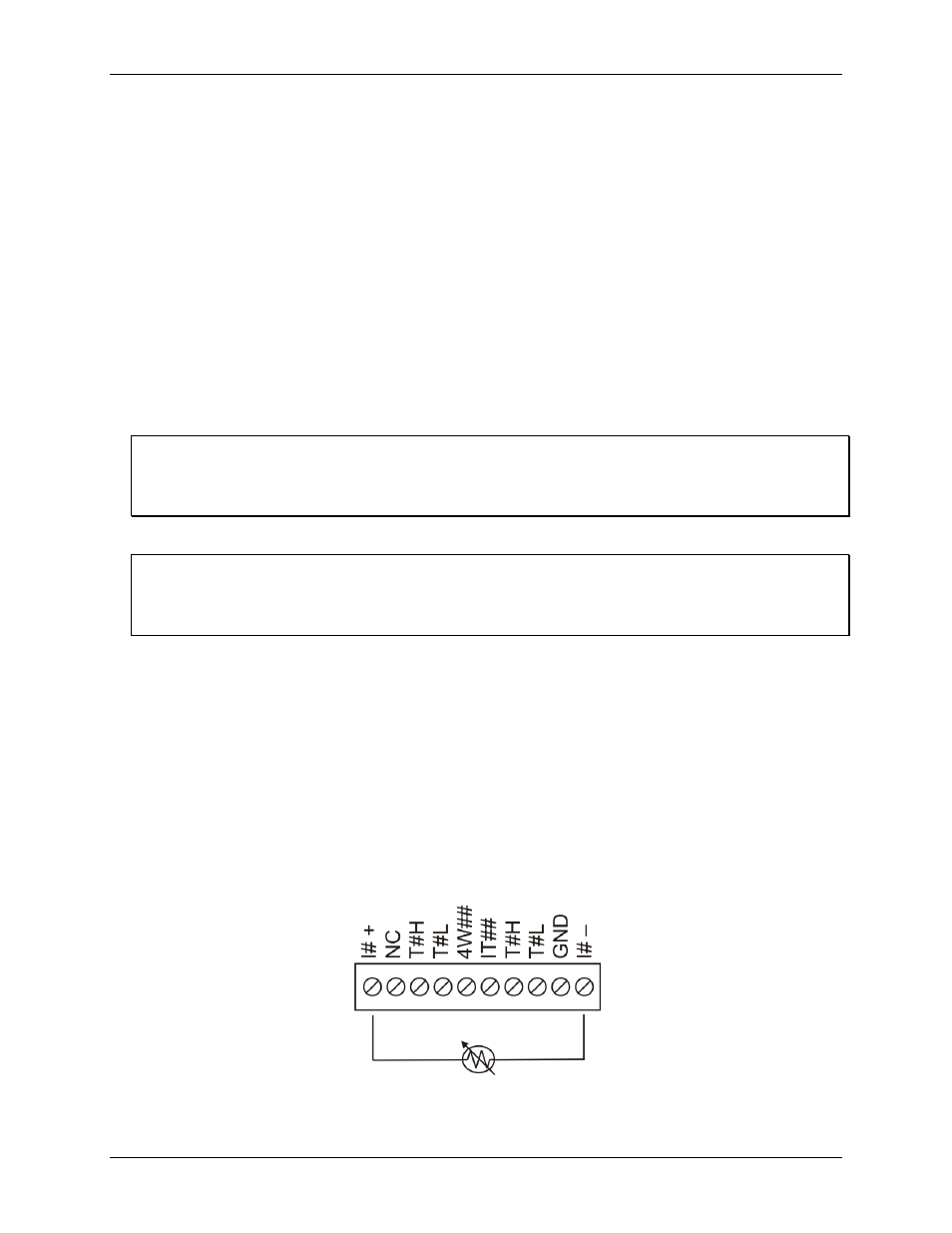
Two-wire, single-sensor
A two-wire single-sensor measurement configuration is shown in Figure 4.
Figure 4. Two-wire, single RTD or thermistor sensor measurement configuration
When you select a two-wire single sensor configuration with InstaCal, connections to T#H and T#L are made
internally.