Data linearization, External components, Screw terminals – Measurement Computing USB-TEMP-AI User Manual
Page 18: Usb connector, Leds
USB-TEMP-AI User's Guide
Functional Details
18
Data linearization
An on-board microcontroller automatically performs linearization on RTD and thermistor measurements.
RTD measurements are linearized using a Callendar-Van Dusen coefficients algorithm (you select DIN,
SAMA, or ITS-90).
Thermistor measurements are linearized using a Steinhart-Hart linearization algorithm (you supply the
coefficients from the sensor manufacturer's data sheet).
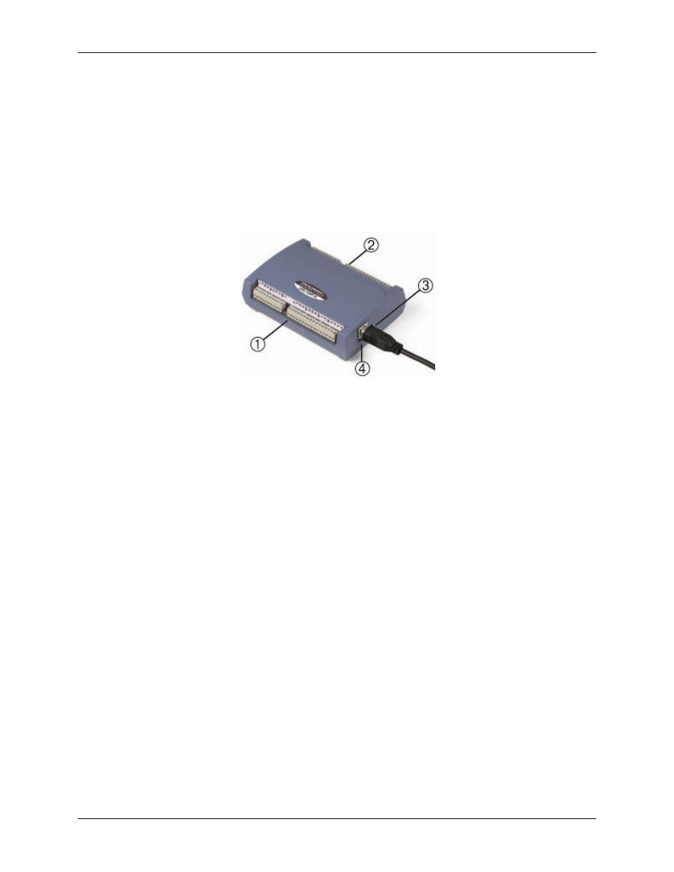
External components
The USB-5203 has the following external components, as shown in Figure 12.
1
Screw terminal pins 1 to 26
3
LEDs: Activity (top) and Power (bottom)
2
Screw terminal pins 27 to 52
4
USB connector
Figure 12.External component locations
Screw terminals
Use the screw terminals for connecting temperature sensors and digital I/O lines. These terminals also provide
ground and power output connections. Refer to the "Error! Reference source not found." chapter for screw
erminal descriptions.
USB connector
The USB connector provides +5V power and communication. No external power supply is required.
LEDs
USB-TEMP-AI has two LEDs –
Activity
and
Power
.
The
Activity
LED (top) blinks when data is transferred.
The
Power
LED (bottom) turns on when the device is receiving power from the USB cable .