Digital i/o connections – Measurement Computing USB-TC User Manual
Page 12
USB-TC User's Guide
Sensor Connections
12
Digital I/O connections
You can connect up to eight digital I/O lines to the screw terminals labeled
DIO0
to
DIO7
. You can configure
each digital bit for either input or output. All digital I/O lines are pulled up to +5V with a 47 kΩ resistor
(default). You can request the factory to configure the resistor for pull-down to ground if desired.
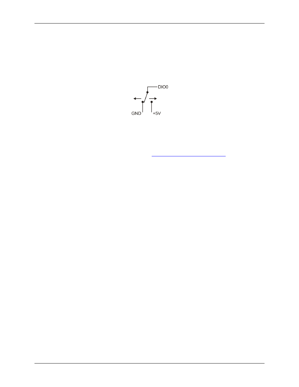
When you configure the digital bits for input, you can use the USB-TC digital I/O terminals to detect the state
of any TTL-level input. Refer to the schematic shown in Figure 4. If you set the switch to the +5V input, DIO0
reads TRUE (1). If you move the switch to GND, DIO0 reads FALSE (0).
Figure 4. Schematic showing switch detection by digital channel DIO0
All ground pins are isolated from earth ground. If a connection is made to earth ground when using digital I/O
and conductive thermocouples, the thermocouples are no longer isolated. In this case, thermocouples must not
be connected to any conductive surfaces that may be referenced to earth ground
For general information regarding digital signal connections and digital I/O techniques, refer to the Guide to
DAQ Signal Connections (available on our web site