Sensor connections, Screw terminal pinout, Thermocouple input – Measurement Computing USB-TC User Manual
Page 10: Cjc sensors
10
Chapter 3
Sensor Connections
The USB-TC supports type J, K, R, S, T, N, E, and B thermocouples.
Thermocouple selection
The thermocouple type you select will depend on your application needs. Review the temperature ranges and
accuracies of each type to determine which is best suited for your application.
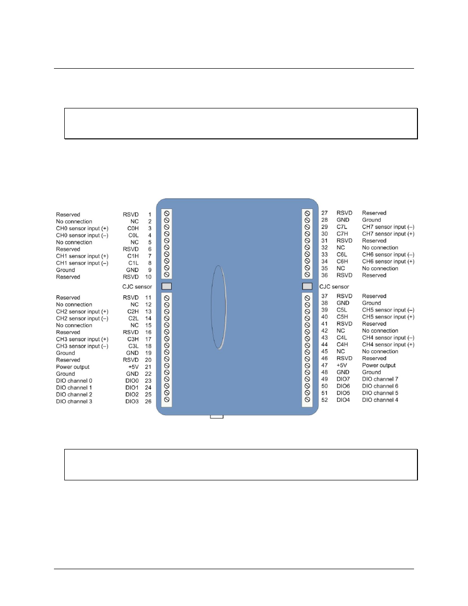
Screw terminal pinout
The USB-TC has four rows of screw terminals — two rows on the top edge of the housing, and two rows on the
bottom edge. Each row has 26 connections. Between each bank of screw terminals are two integrated CJC
sensors used for thermocouple measurements. Signals are identified in Figure 2.
Figure 2. Screw terminal pinout
Use 16 AWG to 30 AWG wire for your signal connections.
Tighten screw terminal connections
When making connections to the screw terminals, be sure to tighten the screw until tight. Simply touching the
top of the screw terminal is not sufficient to make a proper connection.
Thermocouple input
You can connect up to eight thermocouples to the differential sensor inputs (
C0H
/
C0L
to
C7H
/
C7L
). The device
supports type J, K, R, S, T, N, E, and B thermocouples.
CJC sensors
The USB-TC has two built in high-resolution temperature sensors. One sensor is located on the right side of the
package, and one sensor is located at the left side.