Introducing the usb-dio24h/37, Overview: usb-dio24h/37 features, Usb-dio24h/37 block diagram – Measurement Computing USB-DIO24H/37 User Manual
Page 6
6
Chapter 1
Introducing the USB-DIO24H/37
Overview: USB-DIO24H/37 features
This manual explains how to install, configure and use the USB-DIO24H/37 digital I/O board. You can use this
board in a variety of digital applications to control logic devices such as switches, gauges, relays, pumps, and
sensors.
The USB-DIO24H/37 is a USB 2.0 low-speed device supported under popular Microsoft
®
Windows
®
operating
systems. It is designed for USB 1.1 ports, and was tested for full compatibility with both USB 1.1 and USB 2.0
ports.
The USB-DIO24H/37 is a high drive, 24-line digital I/O device that includes one 32-bit external event counter.
Power is supplied by the +5 volt USB supply from your computer. No external power is required.
Digital I/O lines are accessed through a 37-pin connector. Each digital port can be configured for either input or
output. Digital channels are pulled up to +5V with 47k resistors.
The control register that sets the direction of the I/O ports is an emulation of the 82C55 in mode 0 (only). The
74FCT244 outputs are high-drive TTL, capable of sourcing 15 mA and sinking 64 mA.
The USB-DIO24H/37 board is completely plug-and-play, with no jumpers or switches to set. All board
addresses are set by your system's plug-and-play software.
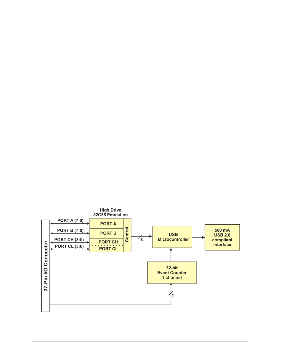
USB-DIO24H/37 block diagram
USB-DIO24H/37 functions are illustrated in the block diagram shown here.
Figure 1. USB-DIO24H/37 functional block diagram