Cables, Field wiring, signal termination and conditioning, Ge 11 – Measurement Computing USB-DIO24H/37 User Manual
Page 11
USB-DIO24H/37 User's Guide
Installing the USB-DIO24H/37
11
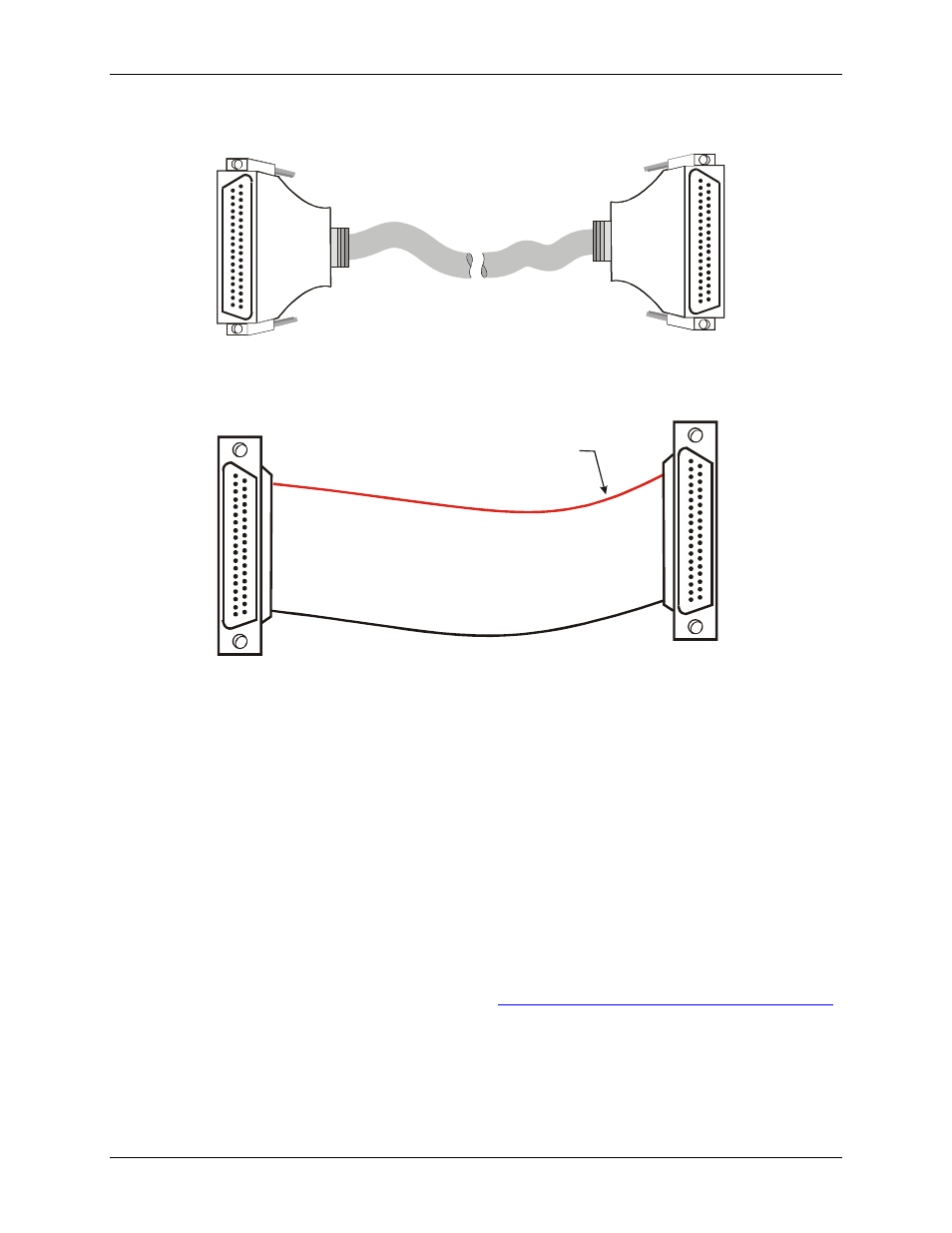
Cables
37
19
20
1
20
1
37
19
37
20
1
20
1
37
19
Figure 3. C37FFS-x cable
20
1
37
19
20
1
37
19
The red stripe
identifies pin # 1
Figure 4. C37FF-x cable
Field wiring, signal termination and conditioning
You can connect the USB-DIO24H/37 to the following accessory boards using the C37FF-x or C37FFS-x
cable.
SCB-37 – 37-conductor, shielded signal connection/screw terminal box.
CIO-MINI37 – 37-pin screw terminal board.
CIO-MINI37-VERT – 37-pin screw terminal board with vertical 37-pin male D connector.
CIO-ERB08 – Eight Form C, 6A relays.
CIO-SERB08 – 8 Form C relays, 10 Amp, relay accessory board with socketed and field-replaceable
relays.
CIO-ERB24 – 24 Form C, 6A relays.
CIO-SPADE50 — 16" X 4" termination panel which mates with both 37-pin and 50-pin connectors.
SSR-RACK08 – 24-channel solid state I/O module rack.
SSR-RACK24 – 24-channel solid state I/O module rack.
Details on these products are available on our web sit