Usb connector, Strain relief slot for usb cable, High-voltage applications – Measurement Computing USB-2404-10 User Manual
Page 12: Signal source connections
USB-2404-10 User's Guide
Functional Details
12
USB connector
The USB connector provides +5 V power and communication. The voltage supplied through the USB connector
is system-dependent, and may be less than 5 V. No external power supply is required.
LED
The LED indicates the device status. When connected to a USB port, the LED blinks steadily to indicate that
the device is initialized and receiving power. Refer to the following table for the possible LED states.
LED States
LED State
device status
Not lit
The device is not connected to a USB port or hub.
Continuous single-blink
The device is operating normally.
Continuous double-blink
The device is connected to a USB 1.1 Full-Speed port or hub, which may affect
performance.
Optimum performance requires connections to a USB 2.0 Hi-Speed host controller
(480 Mbps) and USB 2.0 high-speed hubs.
Strain relief slot for USB cable
Use the strain relief slot to keep the USB cable from disconnecting from the device inadvertently. Feed a tie
wrap through the slot and secure to the USB cable when it is connected to the device.
High-voltage applications
For high voltage applications, we recommend using the ACC-160 backshell to ensure that the terminals are not
accessible. The backshell also provides strain relief to protect the screw terminals.
Figure 4. Connector backshell (ACC-160 accessory)
Additional details on this product are available on our web site
Signal source connections
You can connect ground-referenced or floating signal sources to the USB-2404-10.
Connect the positive signal of the signal source to the CH+ screw terminal.
Connect the negative signal of the signal source to the CH– screw terminal.
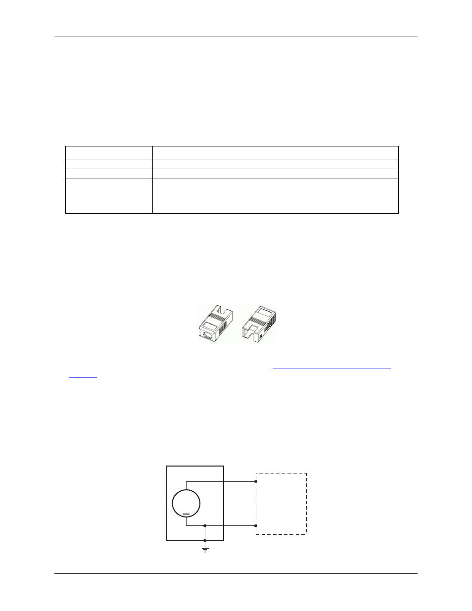
The following figures show the connections between the USB-2404-10 and both a grounded signal source and a
floating signal source.
Figure 5. Connecting a grounded signal source
Signal
Source
+
CH+
CH-
USB-2404-10