Functional details, Components, Screw terminals (ch0 to ch3) – Measurement Computing USB-2404-10 User Manual
Page 11: Chapter 3
11
Chapter 3
Functional Details
Components
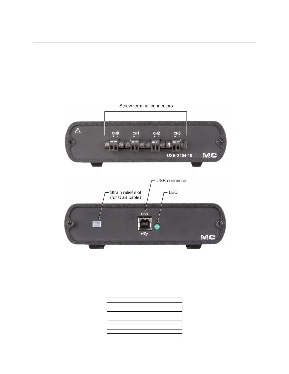
The USB-2404-10 has the following external components:
Screw terminal connectors
USB port
LED
Strain relief slot for USB cable
Figure 2. Front panel (Screw terminal connections)
Figure 3. Rear panel (USB connection and LED)
Screw terminals (CH0 to CH3)
The USB-2404-10 has four 2-terminal detachable screw terminals for connection to four isolated analog inputs.
The maximum sampling rate is 50 kS/s per channel, and the input voltage range is ±10 V, nominal. The
channels may be sampled individually or simultaneously. Signal assignments are listed in the following table.
Screw terminal pin assignments
Screw terminal
Signal
0
CH0+ (CH0 IN HI)
1
CH0
– (CH0 IN LO)
0
CH1+ (CH1 IN HI)
1
CH1
– (CH1 IN LO)
0
CH2+ (CH2 IN HI)
1
CH2
– (CH2 IN LO)
0
CH3+ (CH3 IN HI)
1
CH3
– (CH3 IN LO)
Use 16 AWG to 28 AWG wires to connect signals to the device.