Analog output, External clock i/o, Digital i/o – Measurement Computing USB-1608GX-2AO User Manual
Page 12
USB-1608GX-2AO User's Guide
Functional Details
12
An example of a 4-element list is shown in the table below.
Sample channel-gain queue list
Element
Channel
Range
Mode
0
CH5
BIP5V
SE
1
CH1
BIP10V
DIFF
2
CH15
BIP1V
SE
3
CH5
BIP5V
SE
Carefully match the gain to the expected voltage range on the associated channel or an over range condition
may occur. Although this condition does not damage the device, it does produce a useless full-scale reading,
and can introduce a long recovery time due to saturation of the input channel.
For more information about analog signal connections
For more information about analog input connections, refer to the Guide to DAQ Signal Connections (available
on our web site
Analog output
The two 16-bit analog outputs (
AOUT0
and
AOUT1
) can be updated simultaneously at a rate of 250 kS/s per
channel. One output can be updated at a rate of 500 kS/s. The output range is fixed at ±10 V. The outputs
default to 0 V when the host computer is shut down or suspended, or when a reset command is issued to the
device.
External clock I/O
The device has one external clock input (
AICKI
) and one external clock output (
AICKO
) for analog inputs, and
one external clock input (
AOCKI
) and one external clock output (
AOCKO
) for analog outputs.
You can connect an external clock signal to
AICKI
and/or
AOCKI
.
When using an external clock,
AICKO
outputs the pulse generated from
AICKI
, and
AOCKO
pin outputs the
pulse generated from
AOCKI
.
When using the internal clock,
AICKO
outputs the
ADC scan clock, and
AOCKO
outputs the
DAC scan
clock.
Digital I/O
You can connect up to eight digital I/O lines to
DIO0
through
DIO7
. Each digital channel is individually
configurable for input or output. The digital I/O terminals can detect the state of any TTL-level input. Refer to
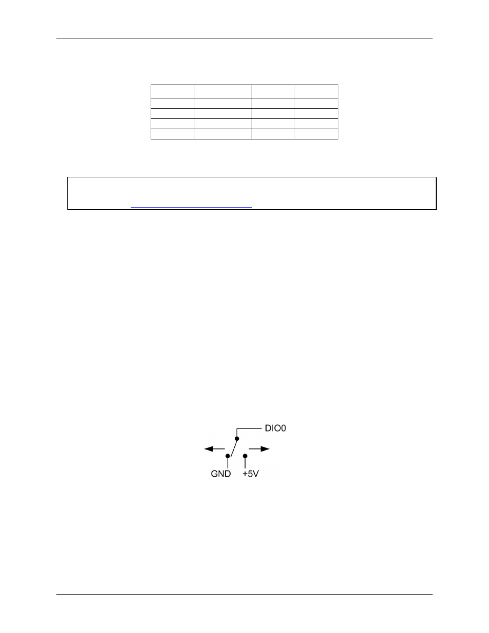
the schematic shown in Figure 7.
Figure 7. Schematic showing switch detection by digital channel DIO0
If you set the switch to the +5 V input, DIO0 reads TRUE (1). If you move the switch to GND, DIO0 reads
FALSE (0).