Signal connections, Analog inputs, Single-ended configuration – Measurement Computing USB-1208LS User Manual
Page 11: Differential configuration
USB-1208LS User's Guide
Functional Details
11
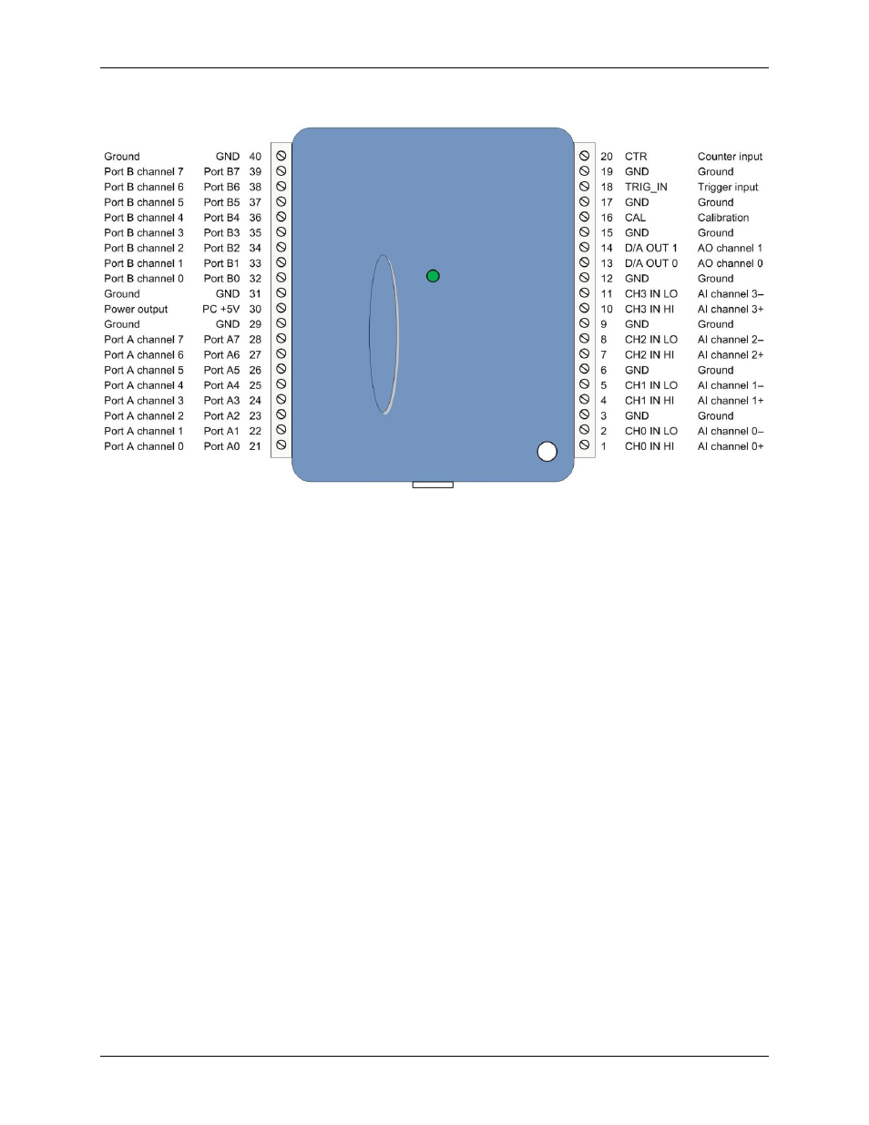
The differential mode pinout is shown in Figure 4.
Figure 4. Differential mode pinout
Signal connections
Analog inputs
You can connect up to eight analog input connections to the screw terminal containing pins 1 to 20 (
CH0 IN
through
CH7 IN
).
You can configure the analog input channels as eight single-ended channels or four differential channels. When
configured for differential mode, each analog input has 12-bit resolution. When configured for single-ended
mode, each analog input has 11-bit resolution, due to restrictions imposed by the A/D converter.
Single-ended configuration
When configured for single-ended input mode, eight analog channels are available. The input signal is
referenced to signal ground (GND), and delivered through two wires:
Connect the wire carrying the signal to be measured to
CH# IN
.
Connect the second wire to
GND
.
The input range for single-ended mode is ±10V.
To perform a single-ended measurement using differential channels, connect the signal to the "
CH# IN HI
"
input, and ground the associated "
CH# IN LO
" input.
Differential configuration
When configured for differential input mode, four analog channels are available. In differential mode, the input
signal is measured with respect to the low input, and delivered through three wires:
Connect the wire carrying the signal to be measured
to CH# IN HI
.
Connect the wire carrying the reference signal to
CH# IN LO
.
Connect the third wire to
GND
.
A low-noise precision programmable gain amplifier (PGA) is available on differential channels to provide gains
of up to 20 and a dynamic range of up to 12-bits. Differential mode input voltage ranges are ±20 V, ±10 V,
±5 V, ±4 V, ±2.5 V, ±2.0 V, 1.25 V, and ±1.0 V.