Usb connector, Screw terminal wiring – Measurement Computing USB-1208LS User Manual
Page 10
USB-1208LS User's Guide
Functional Details
10
USB connector
The USB connector is on the right side of the USB-1208LS housing. This connector provides +5V power and
communication. The voltage supplied through the USB connector is system-dependent, and may be less than
5V. No external power supply is required.
LED
The LED on the front of the housing indicates the communication status of the USB-1208LS. It uses up to
5 mA of current and cannot be disabled. The table below defines the function of the LED.
LED illumination
LED Illumination
Indication
Steady green
The USB-1208LS is connected to a computer or external USB hub.
Blinks continuously
Data is being transferred.
Blinks three times
Initial communication is established between the USB-1208LS and the computer.
Blinks at a slow rate
The analog input is configured for external trigger. The LED stops blinking and illuminates
steady green when the trigger is received.
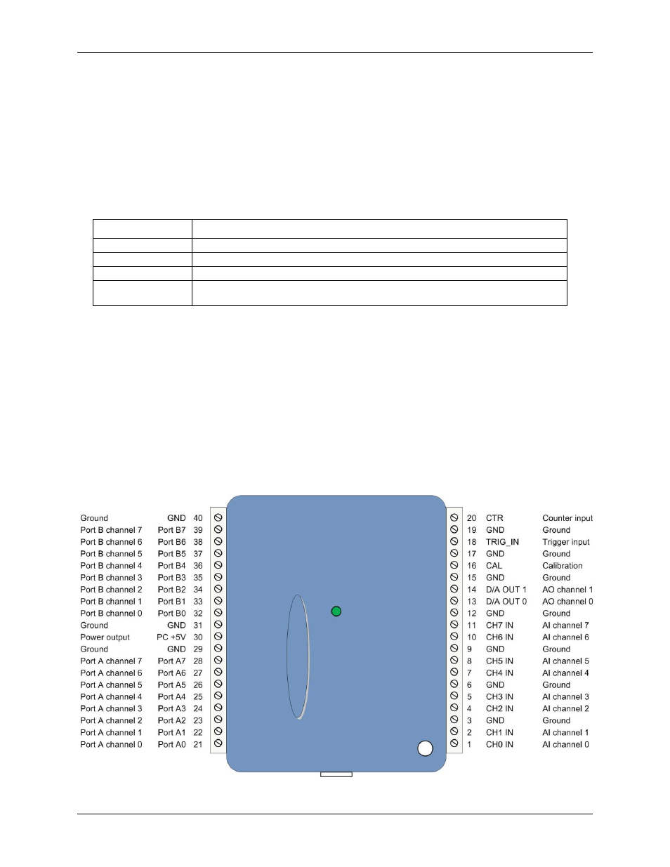
Screw terminal wiring
The screw terminals provide the following connections:
Eight analog inputs (
CH0 IN
to
CH7 IN
)
Two analog outputs (
D/A OUT 0
to
D/A OUT 1
)
16 digital I/O connections (
PortA0
to
Port A7
, and
Port B0
to
Port B7
)
External trigger input (
TRIG_IN
)
External event counter input (
CTR
)
Power output (
PC+5 V
)
Calibration output (
CAL
)
Ground connections (
GND
)
Use 16 AWG to 30 AWG wire when making connections to the screw terminals. The single-ended mode pinout
is shown in Figure 3.
Figure 3. Single-ended mode pinout