Functional details, External components, Usb connector – Measurement Computing USB-1024LS User Manual
Page 11: Screw terminal wiring, Functional details -1, External components -1, Usb connector -1, Led -1, Screw terminal wiring -1
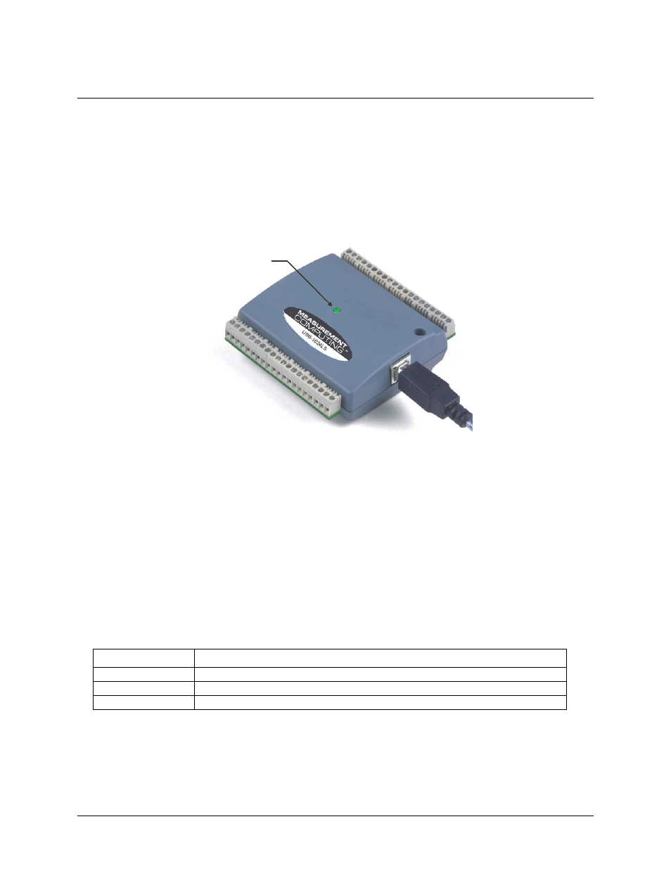
Chapter 3
Functional Details
External components
The USB-1024LS has the following external components, as shown in Figure 3-1.
!
USB connector
!
LED
!
Screw terminal banks (2)
USB
connector / cable
Screw terminal
Pins 21 to 40
Screw terminal
Pins 1 to 20
LED
Figure 3-1. USB-1024LS external components
USB connector
The USB connector is on the right side of the USB-1024LS housing. This connector provides +5 V power and
communication. The voltage supplied through the USB connector is system-dependent, and may be less than +5
V. No external power supply is required.
LED
The LED on the front of the housing indicates the communication status of the USB-1024LS. It uses up to 5
mA of current and cannot be disabled.
defines the function of the USB-1024LS LED.
Table 3-1. LED Illumination
LED Illumination
Indication
Steady green
The USB-1024LS is connected to a computer or external USB hub.
Blinks continuously
Data is being transferred.
Blinks three times
Initial communication is established between the USB-1024LS and the computer.
Screw terminal wiring
The USB-1024LS has two rows of screw terminals – one row on the top edge of the housing, and one row on
the bottom edge. Each screw terminal bank provides 20 connections. Pin numbers are identified in
3-1