Bp40-37 (figure 2-12), Nnector (figure 2-12) – Measurement Computing PCIM-DAS1602/16 User Manual
Page 18
PCIM-DAS1602/16 User's Guide
Installing the PCIM-DAS1602/16
37
19
20
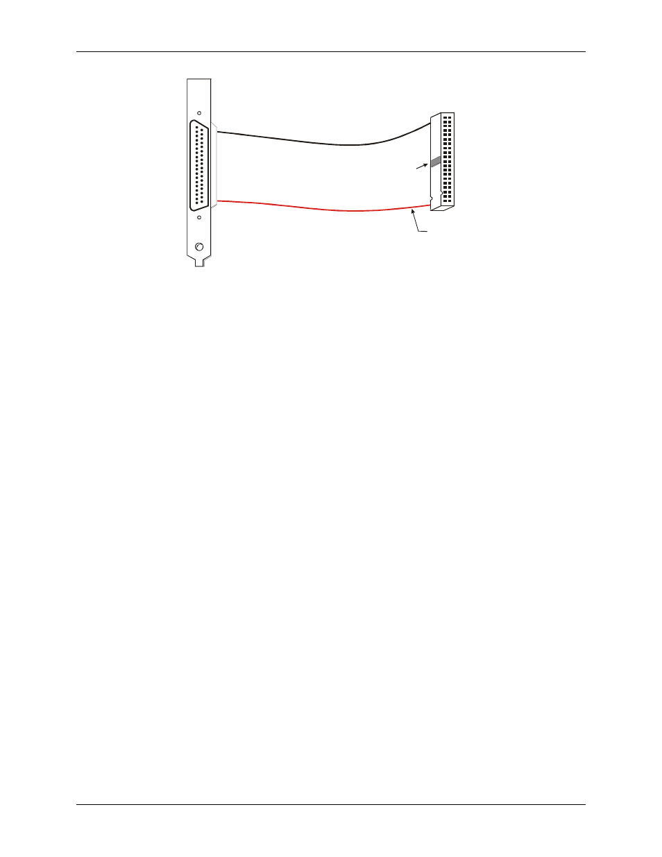
1
The red stripe
identifies pin # 1
2
40
1
39
Key
Figure 2-12. BP40-37 cable
Field wiring, signal termination and signal conditioning
2-9
You can use the following MCC screw terminal boards to terminate field signals and route them into the PCIM-
DAS1602/16 board using the C37FF-x or C37FFS-x cable:
!
CIO-MINI37 – 37-pin screw terminal board.
!
that provides two independent 50-
pin connections.
MC the PCIM-DAS1602/16 board:
!
ISO-RACK16 – Isolated 16-channel, 5B module rack for analog signal conditioning and expansion.
!
ISO-DA02 – Isolated 2-channel, 5B module rack for analog signal conditioning and expansion.
MCC provides the following digital signal conditioning products for use with the PCIM-DAS1602/16 board:
!
onditioning.
!
CIO-ERB24 – 24-channel, Form C relay accessory board for digital signal conditioning.
!
conditioning.
!
nditioning.
- ACC-300 (7 pages)
- AI-EXP32 (20 pages)
- AI-EXP48 (19 pages)
- BTH-1208LS (30 pages)
- 6K-ERB08 (32 pages)
- BTH-1208LS Quick Start (4 pages)
- 6K-SSR-RACK08 (33 pages)
- BTH-1208LS-OEM (27 pages)
- CB-COM-Digital (68 pages)
- CB-7018 (68 pages)
- CB-7000 Utilities (44 pages)
- CB-7080D (74 pages)
- CB-COM-7033 (44 pages)
- CB-COM-7017 (72 pages)
- CB-COM-7024 (76 pages)
- CB-NAP-7000P (36 pages)
- CIO-DAC02/16 (16 pages)
- CIO-DAC02 (18 pages)
- CB-NAP-7000D (56 pages)
- CIO-DAC16-I (16 pages)
- CIO-DAC16/16 (20 pages)
- CIO-DAS08 (21 pages)
- CIO-DAC16 (20 pages)
- CIO-DAS08/JR (16 pages)
- CIO-DAS08/JR/16 (14 pages)
- CIO-DAS08/JR-AO (16 pages)
- CIO-DAS08-AOM (32 pages)
- CIO-DAS08-PGM (28 pages)
- CIO-DAS16/330 (34 pages)
- CIO-DAS48-I (17 pages)
- CIO-DAS16/M1 (38 pages)
- CIO-DAS48-PGA (18 pages)
- CIO-DAS800 (20 pages)
- CIO-DAS802/16 (22 pages)
- CIO-DAS6402/16 (40 pages)
- CIO-DAS-TEMP (20 pages)
- CIO-DDA06/16 (18 pages)
- CIO-DDA06/JR (17 pages)
- CIO-DIO24H (20 pages)
- CIO-DIO24/CTR3 (21 pages)
- CIO-DI192 (24 pages)
- CIO-DDA06 (21 pages)
- CIO-DIO48 (19 pages)
- CIO-DO192H (16 pages)
- CIO-DIO192 (20 pages)