Channel select switch, Channel select switch -3 – Measurement Computing PCIM-DAS1602/16 User Manual
Page 12
PCIM-DAS1602/16 User's Guide
Installing the PCIM-DAS1602/16
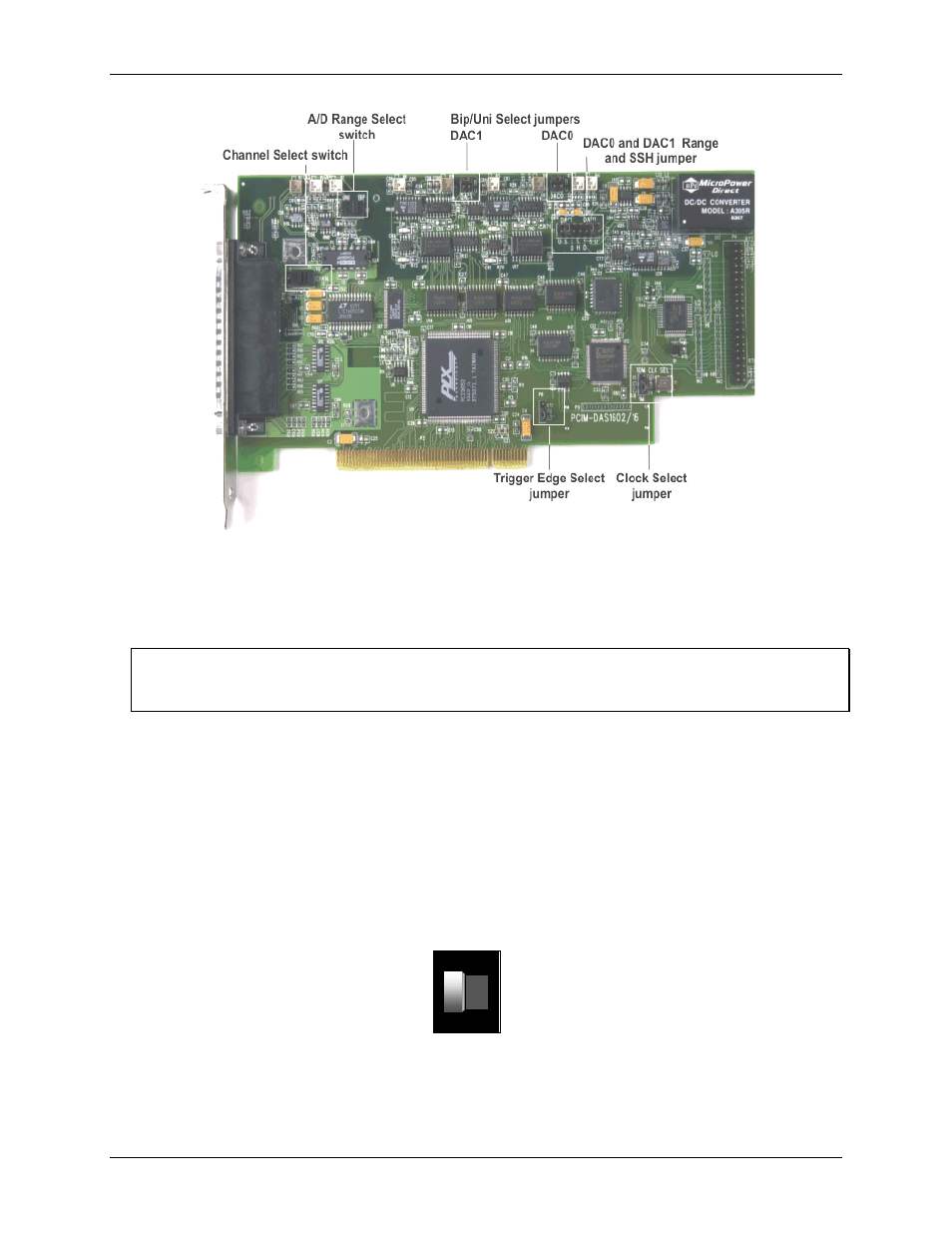
Figure 2-1. PCIM-DAS1602/16 switch and jumper locations
Before installing the PCIM-DAS1602/16 in the computer, verify that the board is configured with the settings
that you want. Review the following information to change the default configuration of a jumper or switch on
the PCIM-DAS1602/16 board.
Board switches are covered by a metal nameplate
To access the Channel Select switch and the A/D Range Select switch, remove the metal nameplate that covers
them. This plate is secured to the board with two screws.
Channel Select switch
Set the channel mode configuration with switch S1. The analog inputs of the PCIM-DAS1602/16 can be
configured as eight differential channels or 16 single-ended channels. Use the single-ended input mode if you
have more than eight analog inputs to sample. Using the differential input mode allows up to 10 volts of
common mode (ground loop) rejection and will provide better noise immunity.
This switch is factory-configured for eight differential inputs. The Channel Select switch shown in
set to the "8" position. To configure for 16 channels, set this switch to 16.
Figure 2-2. 8/16 Channel Select switch
8/16 CHANNEL SELECT SWITCH
16
8
(8 Channels, Differential Input Mode Shown)
2-3