Measurement Computing PCI-INT32 User Manual
Page 13
PCI-INT32 User's Guide
Functional Details
With a pull-down resistor installed, the line is pulled low when the Z8536 is reset. The Z8536 has more than
enough power to drive the line high.
To safeguard against unwanted signal levels, all devices that are controlled by the Z8536 chip should be tied
low or high as required by a 2.2K
Ω resistor. Open positions are located on the board to install resistor Single
Inline Packages (SIP). The positions are marked A, B, and C and are adjacent to the Z8536.
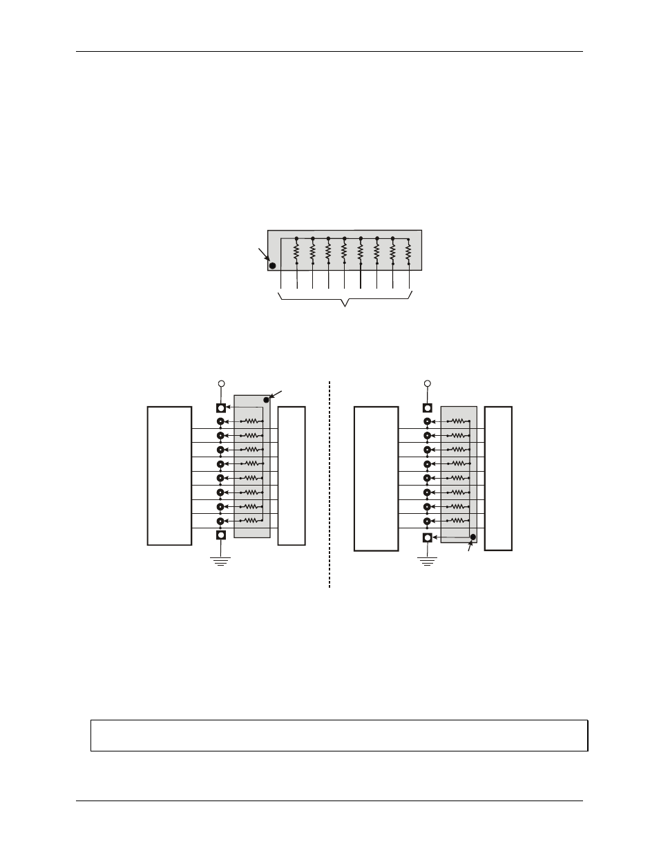
The SIP is made up of eight 2.2 K resistors. One side of each resistor is connected to a single common point and
brought out to a pin. The common line is marked with a dot or line at one end of the SIP. The remaining resistor
ends are brought out to the other eight pins (refer to
).
Figure 4-3. Eight-resistor SIP schematic
2.2KOhm SIP
Dot indicates the
common line
(LO or HI)
I/O Lines
Figure 4-4. Pull-up and pull-down resistor SIP schematic
shows a schematic of an SIP installed in both the pull-up and pull-down positions.
2.2 K SIP installed for pull-up
2.2 K SIP
Dot
+5 VDC
HI
LO
(GND)
n7
U
s
er
C
o
n
n
ec
to
r
Digi
ta
l I/O
L
in
e
s
n5
n4
n3
n2
n1
n0
n6
COM
Digital
I/O
Port
n = A, B, or C
2.2 K SIP
Dot
+5 VDC
HI
LO
(GND)
n7
U
s
er
C
o
n
n
ec
to
r
Digi
ta
l I/O
L
in
e
s
n5
n4
n3
n2
n1
n0
n6
COM
2.2 K SIP installed for pull-down
Digital
I/O
Port
n = A, B, or C
When installed, the SIP establishes either a high or low logic level at each of the eight I/O lines on the port. At
each board location, A, B, and C, there are 10 holes in a line. The hole on one end is marked "HI" and is
connected to +5V. The other end is marked "LO" and is connected to GND. The eight holes in the middle
connect to eight lines of the port, A, B or C.
To pull-up lines, orient the SIP with the common pin (dot) toward the HI end; to pull-down, install the resistor
with the common pin in the LO hole.
Note:
We recommend using 2.2K SIPs (MCC part number SP-K2.29C). Use a different value only if necessary.
4-3