Pull-up/down resistors, Pull-up/down resistors -2 – Measurement Computing PCI-INT32 User Manual
Page 12
PCI-INT32 User's Guide
Functional Details
Caution! The voltages and currents associated with external devices range from less than a hundred mA at a
few volts for a small flash light bulb to 50 Amps at 220 volts for a large electric range. Attempting
to connect either of these devices directly to the PCI-INT32 would destroy the I/O chip.
For general information regarding digital I/O techniques, including signal conditioning and low pass filters,
refer to the Guide to Signal Connections. This document is available on our web site at
).
IMPORTANT
The Z8536 digital I/O chip initializes all ports as inputs on power up and reset. A TTL input is a high
impedance input. If you connect another TTL input device to the Z8536 it will probably be turned ON every
time the Z8536 is reset, or, it might be turned OFF instead. Remember, and Z8536 which is reset is in INPUT
mode.
It cannot be stated often enough to those unfamiliar with the Z8536 — whenever the Z8536 is powered on or
reset, all pins are set to high impedance input.
Output devices such as solid state relays may be switched on whenever the computer is powered-on or reset. To
prevent unwanted switching and to drive all outputs to a known state after power-on or reset, pull pins either
high or low with a pull-up or pull-down resistor.
Pull-up/down resistors
When the Z8536 digital I/O chip is powered-on or reset, the control register is set to a known state. When used
as an output device to control other TTL input devices, the Z8536 applies a voltage level of 0 V for low and
2.5 V to 5 V for high. The device being controlled responds to the output voltage level of the Z8536 chip.
The concept of voltage level of a Z8536 chip in input mode is meaningless. Do not connect a volt meter to the
floating input of a Z8536. It will show you nothing of meaning. In input mode, the Z8536 is in 'high Z' or high
impedance. If your Z8536 was connected to another input chip (the device you are controlling), the inputs of
that chip are left floating whenever the Z8536 is in the input mode. If the inputs of the device you are
controlling are allowed to float, they may float up or down. The direction they float is dependent on the
characteristics of the circuit and is unpredictable. This is why it often appears that the Z8536 has gone 'high'
after power up. The result is that the controlled device gets turned on. That is why you need pull up/down
resistors.
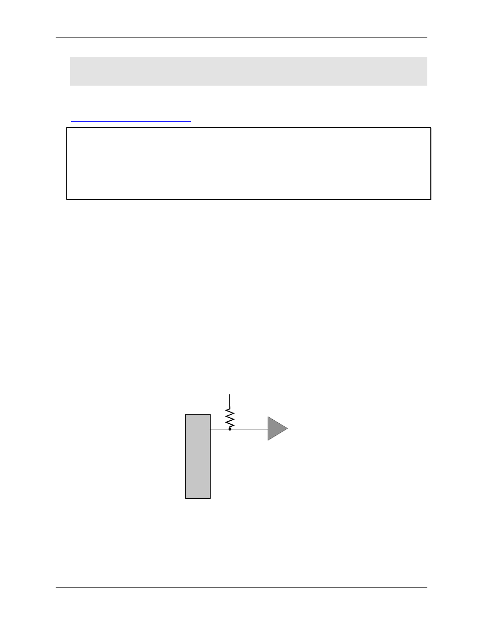
shows a Z8536 digital output with a pull-up resistor attached.
Figure 4-2. Z8536 digital output with pull-up resistor
Z8536
Controlled Device
A0
+5V
2.2K
The pull-up resistor provides a reference to +5V, while its value of 2,200 Ω allows only a little current to flow
through the circuit.
If the Z8536 is reset and enters high impedance input, the line is pulled high. At that point, both the Z8536
AND the device being controlled will sense a high signal. If the Z8536 is in output mode, the Z8536 has more
than enough power to override the pull-up resistor's high signal and drive the line to 0 volts (nominal).
4-2