Installing the hardware – Measurement Computing PCIe-DIO96H User Manual
Page 8
PCIe-DIO96H User's Guide
Installing the PCIe-DIO96H
8
Installing the hardware
The PCIe-DIO96H is completely plug-and-play. There are no switches or jumpers to set on the board.
Configuration is controlled by your system's BIOS. Perform the steps to install your board..
Install the MCC DAQ software before you install your board
The driver needed to run your board is installed with the MCC DAQ software. Therefore, you need to install the
MCC DAQ software before you install your board. Refer to the Quick Start Guide for instructions on installing
the software.
1. Power off and unplug the computer, and remove the cover to expose the expansion slots.
2. Touch any metal part of the computer to discharge static electricity that may be present. Static electricity
can damage the board.
3. Insert the PCIe-DIO96H into an unused x1 PCIe expansion slot.
The PCIe-DIO96H is designed to install into an x1 slot. However, you can also install the board into an
unused x4, x8, or x16 PCIe slot.
Caution! Ensure that you install the board into a PCI Express slot. Installing the PCIe-DIO96H into a
non-PCIe slot can damage both the board and the computer’s motherboard.
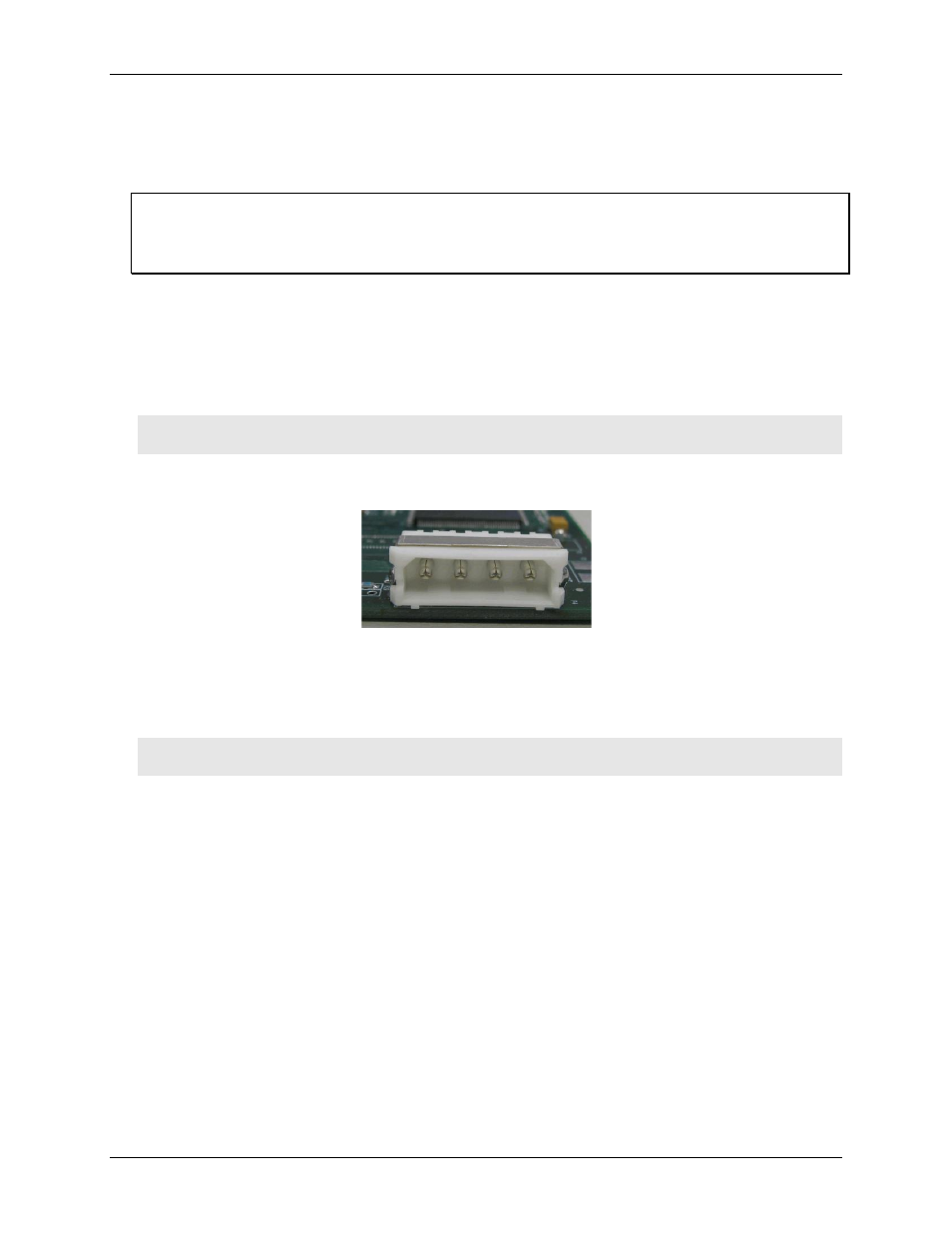
4. Connect the board’s external power connector to one of the computer’s four-pin Molex power connectors.
The board’s Molex power connections are shown here.
Caution! Using an external power supply is not recommended. If external power is used, ensure that the
power supply ground or common is at the same ground potential as the computer power supply.
5. Close your computer and turn it on.
A dialog box opens as the system loads, indicating that new hardware has been detected. The information
file for this board should have already been loaded onto your PC when you installed the Measurement
Computing Data Acquisition Software CD supplied with your board, and should be detected automatically
by Windows. If you have not installed this software, cancel the dialog and install it now.
6. Run InstaCal to test your installation and to configure the pull direction of the digital port resistors.
Refer to the Quick Start Guide that came with your board for information on how to initially set up
InstaCal.
N
o
C
o
n
n
e
c
t
P
C
G
ro
u
n
d
P
C
G
ro
u
n
d
P
C
+
5
V