Signal level control – Measurement Computing PCI-DIO24/LP User Manual
Page 12
PCI-DIO24/LP User's Guide
Functional Details
12
Signal level control
All I/O bits are set to a high impedance input mode on power up and reset. To prevent unwanted signal levels,
and to drive all outputs on the device you are controlling to a known state after power up or reset, install pull-up
or pull-down resistors.
A pull-up resistor pulls all digital pins up to +5 V (high logic level). A pull-down resistor pulls all digital pins
down to 0 V (low logic level).
The PCI-DIO24/LP has open locations where you can install a 2.2 K , eight-resistor single inline package
(SIP) resistor network for each port. The SIP is made up of eight 2.2 K resistors. One side of each resistor is
connected to a single common point and brought out to a pin. The common line is marked with a dot or line at
one end of the SIP. The remaining resistor ends are brought out to the other eight pins (see Figure 3).
2.2 KOhm SIP
Dot
(LO or HI)
I/O Lines
Figure 3. Eight-Resistor SIP Schematic
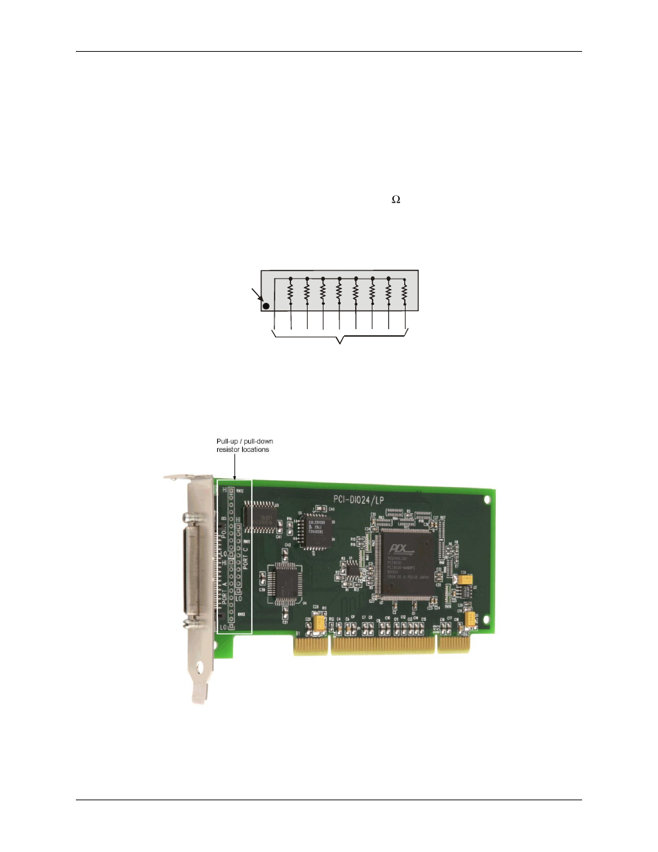
Each port provides 10 holes. Install an SIP on the board at the locations labeled
PORT A
,
PORT B
and
PORT C
Figure 4. Pull-up/down resistor locations
The end labeled
HI
connects to +5 V. The end labeled
LO
connects to GND. The eight holes in the middle (n0 –
n7) connect to the eight lines of the port (PORT A, PORT B, or PORT C). Figure 5 shows an SIP resistor
network installed in both pull-up and pull-down positions.