Signal level control, Pci-dio24h user's guide functional details, Figure 5. eight-resistor sip schematic – Measurement Computing PCI-DIO24H User Manual
Page 13: Port a, Port b, Port c
PCI-DIO24H User's Guide
Functional Details
13
Signal level control
All I/O bits are set to a high impedance input mode on power up and reset. To prevent unwanted signal levels,
and to drive all inputs on the device you are controlling to a known state after power up or reset, install pull-up
or pull-down resistors.
A pull-up resistor pulls all digital pins up to +5 V (high logic level). A pull-down resistor pulls all digital pins
down to 0 V (low logic level).
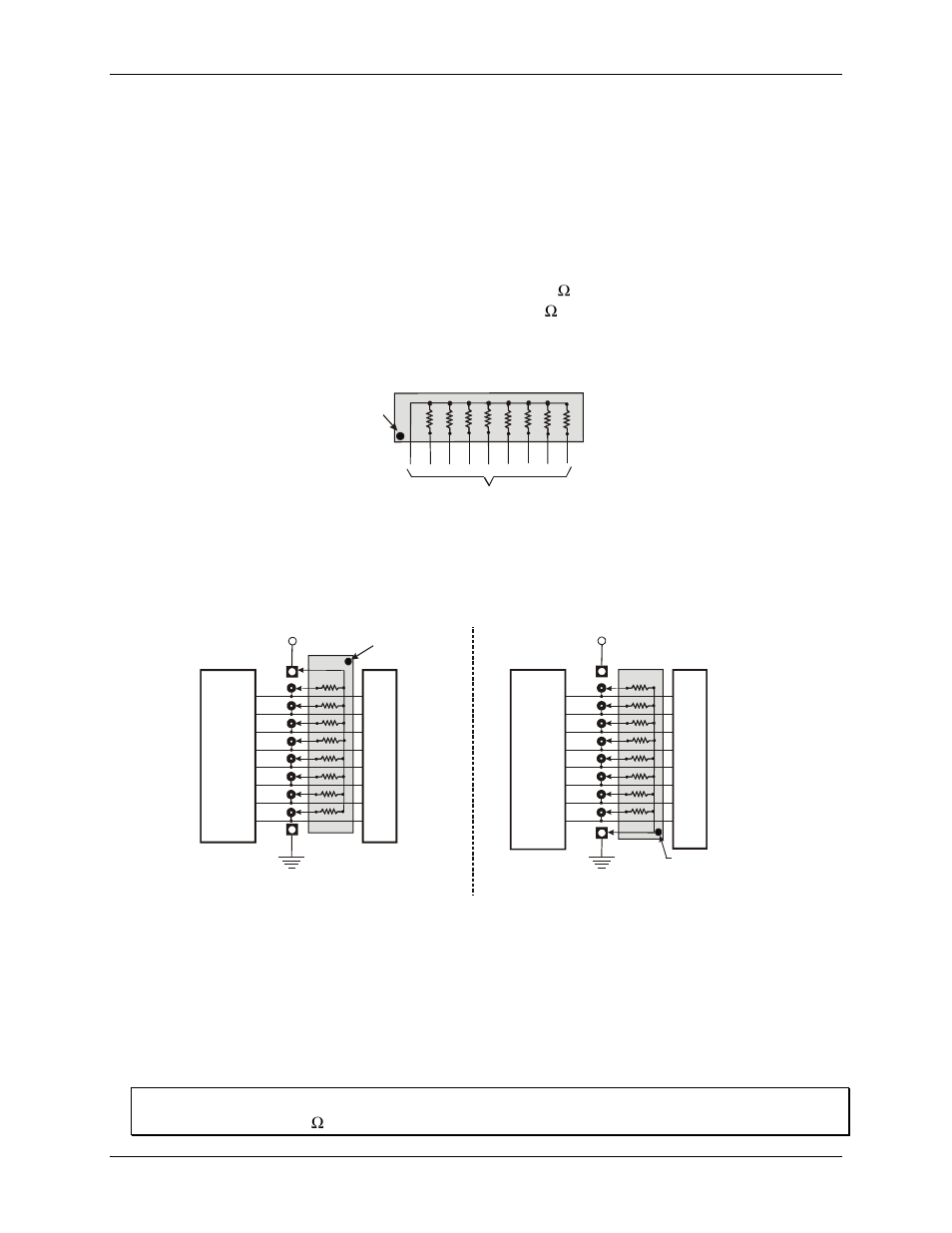
The PCI-DIO24H has open locations where you can install a 2.2 K , eight-resistor single inline package (SIP)
resistor network for each port. The SIP is made up of eight 2.2 K resistors. One side of each resistor is
connected to a single common point and brought out to a pin. The common line is marked with a dot or line at
one end of the SIP. The remaining resistor ends are brought out to the other eight pins (see Figure 5).
2.2KOhm SIP
Dot
(LO or HI)
I/O Lines
Figure 5. Eight-resistor SIP schematic
Install the SIP on the PCI-DIO24H board at the locations labeled
PORT A
,
PORT B
and
PORT C
(adjacent to
the 37-pin connector). Figure 6 shows a schematic of an SIP installed in both the pull-up and pull-down
positions.
2.2 K SIP installed for pull-up
2.2 K SIP
Dot indicates the
common line
+5 VDC
HI
LO
(GND)
n7
U
s
e
r
C
o
n
n
e
c
to
r
D
ig
it
a
l
I/
O
L
in
e
s
n5
n4
n3
n2
n1
n0
n6
COM
Digital
I/O Port
n = A, B, or C
+5 VDC
2.2 K SIP installed for pull-down
2.2 K SIP
Dot indicates the
common line
HI
LO
(GND)
n7
U
s
e
r
C
o
n
n
e
c
to
r
D
ig
it
a
l
I/
O
L
in
e
s
n5
n4
n3
n2
n1
n0
n6
COM
Digital
I/O Port
n = A, B, or C
Figure 6. Pull-up and pull-down resistor SIP schematic
When installed, the SIP establishes either a high or low logic level at each of the eight I/O lines on the port. At
each board location, A, B, and C, there are 10 holes in a line. The hole on one end is marked "HI" and is
connected to +5V. The other end is marked "LO" and is connected to GND. The eight holes in the middle
connect to eight lines of the port, A, B or C.
To pull-up lines, orient the SIP with the common pin (dot) toward the HI end; to pull-down, install the resistor
with the common pin in the LO hole.
Note:
We recommend using 2.2K SIPs (MCC part number SP-K2.29C). Use a different value only if necessary.